| Kellett KD-1 1934 |  |
 |
|
| Kellett KD-1 1934 | |
|
|
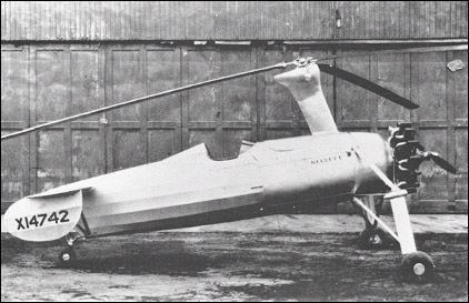
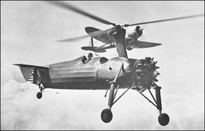
About 1935 Kellett announced a new model, the KD-l. The "D" denoted Direct Control. This meant that the control of the autogiro did not depend on airspeed for effectiveness. As long as the rotor turned, control was adequate- even at zero airspeed. Control responses came from tilting the entire rotor head with the control stick in the direction that control was desired. This was similar to the Pitcairn PA-22, PA-35, PA-36, PA-34, PA-39 and XOP-2. Actually, Wallace Kellett and Chief Engineer Dick Prewitt went to Europe to see Cierva's C-30 Autogiro. The KD-1 was made more nearly a copy to that autogiro. Several departures from earlier Kellett machines were noticeable. Seating was now tandem in open cockpits. The landing gear was nearly directly under the engine. The engine selected was a locally manufactured seven-cylinder radial air cooled Jacobs L4MA-7, developing 225hp. The rear of the engine was especially modified to drive the rotor prior to takeoff using the engine starter pad. Rotor blades were different from earlier Kellett blades. The chord was reduced to 0.3m from K-3, K-4's 0.6m. The airfoil section was a Goettingen 606. All other Kellett rotor airfoils had been nearly symmetrical while this one had nearly a flat underside. The upper curve was a high lift airfoil. Attachment of the ribs to the steel tube spar departed from the pinned-on method previously used in favor of the spot welded attachment used by Pitcairn. The ribs were routed from specially made 3-ply wood using vertical grain mahogany over horizontal grain birch. The mahogany layers were 1/16" thick and the birch 1/8". The trailing edge was spruce, the leading edge was ash. The entire blade was covered with 1/32" mahogany 3-ply, then covered with balloon cloth and doped to a smooth finish. The blades were balanced chordwise with a brass bar right at the nose and balanced spanwise by filling any of three boxes near the blade tip with lead shot as required. The number of blades was reduced to three. The droop cables were eliminated by installing droop stops at the hub. Blade dampers now inside the spar working on a cam at the hub kept the blades spaced equally from each other. As the blades tried to lead or lag the damper came into play returning the blade to the proper spacing. The rotor hub was neat and simple. The run-up gears were now inside a housing containing oil for lubrication. The rotor support was simple in design. Only one large, round, heat-treated steel tube carried the flight loads to the fuselage. A streamlined aluminum fairing housed the support or pylon tube as well as the vertical drive shaft. At the bottom of the shaft within the cowl, a rotor brake was provided to stop the rotor after landing. The rest of the rotor spinup system consisted of a power takeoff housing on the back of the engine. A leather-lined cone clutch permitted the engine to be engaged slowly and smoothly and quickly disengaged before takeoff. The horizontal shaft passed through the firewall to an intermediate gearbox where the drive angle was changed from horizontal to vertical. On the output side of this box was an overrunning clutch to permit the rotor to turn if the engine clutch should fail to disengage on takeoff. A torque-limiting shear pin fastened the vertical shaft to the gear box. The pin would shear if excess torque was applied to the rotor on run-up. If the pin should fail when the rotor was near takeoff rpm, a takeoff could still be made. The rotor rpm would increase on the takeoff run. A pin could be easily replaced when back on the ground. The fuselage was built up of gas welded steel tubing heavily faired with light weight aluminum bows and longitudinal members. The forward part was covered with sheet aluminum. The fuel tanks formed the fairing and covering for the sides of the fuselage at the front cockpit. The rest of the fuselage was fabric covered. The horizontal tail was assembled from solid spruce spars with built-up ribs with cap strips and plywood webs. The stabilizers were internally braced with steel rods. The leading edge was made from a round steel tube and covered with plywood from the leading edge to the front spar, top and bottom. The tip and trailing edge was formed from a round steel tube that was gradually formed into a streamline shape as it left the rear spar. A handhold was provided in the tip aft of the front spar for ground handling. The rudder and vertical tail surfaces were welded steel tube assemblies. All surfaces were fabric covered and doped. The landing gear was a wide tread type with Bendix air and oil shock struts. The tires were 8:00 x 15 with 0.15m Hayes Industries mechanical brakes. The tail wheel was a 0.25m with a swivel device that could be locked in the steerable position. The tail shock strut was an air-oil type. The rest of the tail group consisted of a small rudder carrying the fuselage side shape to a rounded ending. The horizontal tail was ground-adjustable. The left side was installed with the airfoil in its normal upright position while the right hand side had the airfoil inverted. This imparted a twist to the fuselage which directly opposed the propeller torque. As power was applied and the air stream from the propeller increased, the right side wanted to "lift down" while the left lifted in the "up" position. When the power and air stream was reduced, the lift reduced. The adjustment also permitted various angles of incidence to be selected. They could be used to compensate for c.g. changes to the autogiro through its life as well as to compensate for propeller torque. Because the rotor was not driven in flight, there was no rotor torque transmitted to the fuselage. Two vertical fixed surfaces were attached to the bottom of the horizontal stabilizers where there was no risk of their being struck by the rotor. The horizontal stabilizers were supported by two aluminum streamlined struts on either side extending down to the bottom longerons. Cockpit controls were the same as those found in any open cockpit airplane with certain additions. The rear cockpit control stick was provided with a stick lock where the stick was placed when the rotor was at rest or below approximately 100 rpm. The stick was pushed forward into the lock soon after landing and was kept in the lock while starting the rotor until about 100 rpm was reached (flight rotor rpm was 210). There was no danger of getting the stick into the lock in flight because the lock was at the extreme forward end of the stick travel. A clutch lever was located just under the throttle on the left side of the cockpit so that no time was lost in getting the throttle wide open when the clutch was released. Rudder pedals were used to steer the tail wheel while on the ground. In flight the pedals would aid in making a tighter turn although they were not needed for a normal turn. When the stick is rolled either way and the autogiro banked, it would turn in that direction. Rolling out a turn could be done in the same way without adverse yaw. The KD-1 controlled easily with an extremely light touch and was quite sensitive. Longitudinal and lateral bungees were provided to relieve control loads caused by an unbalanced autogiro. The pilot occupied the rear seat and the observer or passenger sat up front. The rear cockpit had an altimeter, airspeed indicator, tachometers for engine and rotor, compass, oil temperature and oil pressure gauges. Glass sight gauges on the rear side of the fuel tanks provided fuel quantity information. These could only be seen from the rear cockpit. A Jacobs L4MB7 delivered 225hp through fixed-pitch Curtiss-Reed propeller. A Heywood air starter cranked the engine. CAA Certification was obtained. Only one KD-1 was built. At the same time that the KD-1 was announced, Kellett moved from Philadelphia's Municipal Airport which was frequently flooded by the nearby Delaware River. The move was to a 2800 square meters building about a mile away on Island Road. After the retirement of the prototype KD-1 about 1943, it rested many years in the basement storage area of Philadelphia's Commercial Museum. It was rescued in 1953 by the author at the request of Wallace Kellett who had a desire to restore it for exhibition. Unfortunately, Mr. Kellett had an untimely death before the restoration was begun. Kellett management had no interest in the project. It was stored, along with many famous cousins, in a barn on Harold Pitcairn's estate. In 1959 a fire destroyed the barn and all the autogiros including the KD-1. Some of its parts were saved and put into a reborn KD1 bearing serial number 101 in 1959. Kellett extensively demonstrated the "new" KD-1 in 1960, planning to go into production again. G.Townson "Autogiro. The Story of the Windmill Plane", 1985
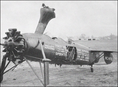
The products of the Kellett Autogiro Corporation, formed in 1929, showed strongly the influence of the early Cierva autogiros, for which the American company held a manufacturing licence. Kellett's first autogiro was the 2-seat K-2 of 1931, but its best-known design was the KD-1 which first appeared late in 1934. This was a direct control autogiro (hence the D in the designation) and was also a 2-seater, the cockpits in this case being open and placed in tandem. The pylon for the 3-blade main rotor was situated immediately in front of the forward cockpit, and the blades could be folded back over the fuselage. Standard powerplant for the KD-1A production version was the 225hp Jacobs L-4-MA radial engine, the torque from which was corrected by giving the port and starboard tailplane halves opposing incidences. On 19 May 1939 a single-seat converted KD-1A, still with an open cockpit, carried out a demonstration flight from the centre of Washington to the city's Hoover Airport with a cargo of mail. Two months later, on 6 July, a similar aircraft in Eastern Air Lines colours and with an enclosed cockpit commenced the first-ever scheduled air mail service by a rotary-winged aeroplane, between the Philadelphia Post Office and nearby Camden Airport. This version of the autogiro was known as the KD-1B, and it continued to operate the service for about 12 months. In 1935 the U.S. Army Air Corps acquired one KD-1A for trials, giving it the designation YG-1. Subsequently it received one YG-1A, seven YG-1B's and seven XO-60's. One of the YG-iB's was converted to YG-1C and later to XR-2 with a 330hp Jacobs L-6 engine, and another to XR-3 with a new rotor mounting after the XR-2 had suffered destruction due to ground resonance troubles. The XO-60 (later YO-60) was a further development in which the chief differences were a 300hp Jacobs R-9I5-3 engine, a bulged Perspex cabin enclosure and observation windows in the fuselage floor. Because of the advent of successful helicopter designs, notably those of Sikorsky, further military development of the YO-60 was discontinued after 1943. The Japanese government, after acquiring and testing a KD-1A in 1939, turned the aircraft over to the Kayaba Industrial Co, which subsequently built an inline-engined version of the aircraft as the Ka.1. This was powered by a 240hp Kobe engine (licence version of the German Argus As.10C); the first Ka.1 was flown on 26 May 1941 and eventually some two hundred and forty aircraft of this type were built. They were employed during World War 2 by the Imperial Japanese Army for artillery observation and cooperation duties, and by the Navy for coastal or carrier-based antisubmarine patrol carrying two 60kg bombs or depth charges. One Ka.1 was modified for trials with small auxiliary rockets at the tips of the rotor blades. Some fifteen years after the end of World War 2 the KD-1A design was resurrected and offered as a production autogiro, either in its original open-cockpit form or with a YO-60-type cabin hood and a fully-cowled Jacobs R-775-9 of 225hp. K.Munson "Helicopters And Other Rotorcraft Since 1907", 1968
|