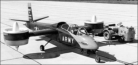
Doak Model 16 was the first VTOL aircraft to demonstrate the tilt duct concept. It was built by the Doak Aircraft Company of Torrance, CA. The company president, Edmond R. Doak, had experimented with ducted fan and various other air moving principles since 1935. He first proposed a VTOL aircraft using the tilt duct principle to the military as early as 1950. The U.S. Army Transportation Research and Engineering Command purchased a single Doak 16, designated the VZ-4DA, serial number 56-9642. The Army issued the contract to Doak on April 10, 1956.
The basic configuration was a two-place tandem cockpit with a mid-wing, conventional tail, and fixed tricycle landing gear. The most notable feature of the aircraft was the ducted fan located at the tip of each wing. Conventional construction techniques were used throughout the aircraft. The fuselage was made of welded steel tubing and covered with a molded fiberglass skin from the cockpit forward. The aft fuselage, with its much straighter lines, was covered with thin aluminum sheet. The cantilever wing and tail unit were of all metal construction. Major design emphasis was on the wing tip ducts, fans, hovering stability parameters, power transmission system, and pilot controls. To save development costs, Doak incorporated numerous off the shelf items in the design, such as using the landing gear from a Cessna 182, seats from a F-51, duct actuators from T-33 electric flap motors, and the rudder mechanism from an earlier Doak aircraft.
Overall dimensions were 9.75m length, 7.75m wing span (including the ducts), 3m height, and wing area of 8.73m2. The design empty weight was 900kg with a design gross vertical take-off weight of 1170kg. These grew to 1037kg and 1443kg during the life of the program. To keep weight down, the original specification called for the aircraft fuselage to remain uncovered. However, it subsequently was felt that this would severely limit being able to obtain any meaningful forward speed data, and that the added weight would allow for much more valuable data to be collected.
The maximum speed was estimated at 370km/h, with a rate of climb at sea level of 30m/s, 1830m hover ceiling, 1 hour endurance, and 370km range.
The wingtip-mounted ducts were five feet in diameter with a four foot inside diameter. Their construction was of aluminum alloy with a fiberglass leading edge section. Eight fixed pitch fiberglass fan blades turned at a maximum fan speed of 4800 rpm. Ahead of the fan in the forward part of the duct were fourteen fiberglass variable inlet guide vanes. The vane angle varied during hover to modulate the thrust produced by the duct, and thus to obtain roll control. The prop was set back two feet from the front of the duct to prevent airflow separation. Nine stainless steel stator blades located aft of the fan straightened the air flow as it exited the duct.
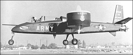
The ducts rotated through 92 degrees, pointing horizontal for forward flight, and pivoting to 2 degrees aft of vertical during hover. The ducts rotated past vertical to compensate for the thrust from the jet exhaust. A switch on the control column initiated the duct rotation. To power the fans, drive shafts traveled through the wing quarter chord. Doak-designed flexible couplings compensated for misalignment and wing flexing.
A Lycoming T-53-L-1 turboshaft engine located in the fuselage just below the wing root provided power. It produced 825hp (some sources stated 840hp). A "T" box on the engine transmitted power to the ducts using a four-inch tubular aluminum shaft and two smaller steel shafts of 3.8cm each.
Flight controls consisted of standard stick and rudder. An electrical and mechanical interlock system controlled all functions for both hovering and forward flight. There were no other cockpit controls. In hover, a cruciform shaped vane in the tail pipe at the rear of the fuselage controlled pitch and yaw by deflecting the engine exhaust. Rotating the inlet guide vanes in the ducts provided roll control by restricting airflow. As the ducts rotated from vertical to horizontal, a mechanical control system gradually phased out control of the inlet guide vanes and left them aligned with the duct airflow. There was no artificial damping or power boost. Doak looked down on any type of automatic stabilization system, feeling that the aircraft should be a satisfactory flying machine without any such equipment. Careful selection of the duct location allowed the fuselage to remain level throughout the transition.
Ground testing began at Torrance Municipal Airport during February 1958. Tests consisted of 32 hours in a test stand, and 18 hours of tethered hovering and taxi tests. The first free hovering flight was performed on February 25.1958. Initial Doak testing at Torrance was completed in June 1958 and was followed by a complete tear down inspection. The aircraft then was transferred to Edwards AFB in October 1958. At Edwards, it performed 50 hours of tests, including transitions at altitudes as great as 1830m. Following these tests, the Army accepted the Doak 16 in September 1959 and transferred it to NASA Langley for further tests.
The Doak 16 demonstrated conventional, vertical, and short take-offs and landings. While the aircraft exhibited some undesirable flight characteristics, only a few were considered fundamental to the Tilt-Duct system and these were solvable. One of the most undesirable characteristics was a nose-up tendency during transition from hovering to forward flight caused by the ducts. Short take-off and landing performance proved to be below expectation. At moderate speeds with partial duct angles, the load distribution across the wing was less than expected. This was because the ducts at the wing tips provided a large part of the total lift, especially at lower airspeeds. Greater drag results when more lift is produced outboard on the wings. The maximum speed demonstrated at sea level was 370km/h, maximum rate of climb at sea level was 20m/s, and the range was 370km.
By late 1960, Doak must have been in serious financial trouble. They sold the patent rights and all engineering files to Douglas Aircraft, in nearby Long Beach (Edmond Doak had worked at Douglas in the 1930s and certainly still had many friends there). Doak finally closed its doors early in 1961. Douglas liked the aircraft and had some ideas for improving it, primarily by installing a larger engine and making numerous structural improvements. They made an unsolicited proposal to the Army in 1961, but could not sell their ideas. The Doak 16 remained at NASA Langley until August of 1972. Eventually it was transferred to the U.S. Army Transportation Command Museum at Fort Eustis, VA, near Newport News, where it is on display.
S.Markman & B.Holder "Straight Up: A History of Vertical Flight", 2000