Aircraft Profile #179. Gloster Javelin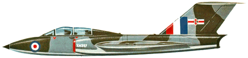 |
|
|
The origin of the Javelin, as far as any aeroplane can be said to have a clearly defined starting point, lay in two Air Ministry specifications, F.43/46 and F.44/46 for an interceptor fighter and a two seater fighter respectively. The Gloster Aircraft Design Team under George Carter, made project studies of both specifications using research information on delta planforms pioneered by Herr Lippisch in Germany. Both projects had delta wings with delta tailplanes and were submitted to the Ministry of Supply in March 1947. Included in the proposals for armament was the recoiless gun, developed at Fort Halstead. This was basically a barrel firing an anti-aircraft shell of 94mm or 114mm forward, whilst simultaneously firing a counter weight of equal mass to the rear, this arrangement preventing any recoil loads being imposed on the airframe. The gun was not reloaded in the air so four or six barrels would have been required. Fitted with proximity fuses, these shells would no doubt have had a devastating effect on an enemy aircraft but the installed weight of the guns was high. With missiles already being developed, the weapon was dropped in favour of the 30mm Aden gun. The Ministry were interested in the Gloster studies and, as a result of further inquiries, two more studies were
Further Ministry requirements were embodied in another brochure before, in February 1948, two new specifications were issued, F.3/48 for the interceptor and F.4/48 for the all weather fighter, F.3/48 was taken up by Hawkers and became the Hunter. In May 1948, the Ministry suggested that Glosters should produce four F.4/48 prototypes and the firm estimated that the first should fly in December 1950, if there were no further changes. Later that year the combat weight was fixed, largely on the engine power available. The choice lay between the Rolls-Royce A.J.65 Avon, then giving 2950kg static thrust, and the Metrovick (later Armstrong Siddeley) F.9 Sapphire, then of 3180kg thrust. The extra power won the day for the Sapphire which was the only engine fitted to the production machines. A final design brochure containing all the agreed features was sent to M.o.S. in August 1948 and in April 1949 an "Instruction to Proceed” was issued for four flying prototypes and one for structural testing. This was subsequently cut to two prototypes, as an economy measure, in November of that year. The impossibility of doing all the development flying on two aircraft eventually dawned on the official mind and the order was increased to five standard and one trainer prototype in
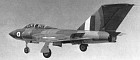
The basic layout of the Javelin, with the fuel and armament in the wings and the crew and engines in the fuselage, was established early in the design studies. The delta tail plane was considered necessary for manoeuvrability at high speed and for control at low speed during take off and landing. It also permitted a longer C.G, travel. In the early stages the tail plane was a slab control with no elevators which was thought to be the best answer to transonic control problems, but information on the North American Sabre showed that conventional elevators were quite effective at these speeds so a trimable tailplane with conventional elevators was fitted. At one stage pivoting wing tip ailerons were shown on the project drawings but these too were eventually replaced by conventional ailerons. The design work was carried out at the Gloster Experimental factory at Bentham. Much of the detail manufacture was done at the parent factory at Hucclecote but the prototype airframes were assembled at Bentham and subsequently taken by road to the Company's Flight Test aerodrome at Moreton Valence. JAVELIN PROTOTYPES The first prototype WD804 was transferred to Moreton Valence in July 1951 where the final system tests took place. During engine
Taxiing trials were begun in the middle of October and on 26th November WD804 took to the air for the first time, late on a clear, cold afternoon. The flight lasted 34 minutes and was a success except for rather severe rudder buffeting. Subsequent flights with wool tufts fitted showed vertical airflows over parts of the fin. These were caused by the confluence of the jet efflux and the flow around the rear fuselage. The trouble was reduced by lengthening the rear fuselage and the jet pipes, but was not finally cured until the fitment of the "pen-nib" fairing at the top of the rear fuselage which was embodied on all Sapphire Sa.6 production aircraft. With this problem overcome, the development flying proceeded smoothly until the 99th flight in July 1952. Sqdn. Ldr. W. A. Waterton, was flying the aircraft when elevator flutter set in, resulting in the loss of both elevators. Due to the generous tailplane area, the aeroplane was still controllable but the electric actuator
This was a serious setback to the development programme, but fortunately the second prototype WD808 was nearly completed. It first flew from Moreton Valence on 20th August, 1952. Naturally the Company was keen to show the aeroplane at the S.B.A.C. display, despite the limitations which had to be imposed until the causes of the first prototype crash had been fully investigated in the air. Waterton flew the machine at the Show and impressed the visitors with a display of low-speed flying. In the autumn of 1952, a flight resonance system, based on vibration generated
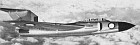
The third prototype, WT827S flew on 7th March 1953, again piloted by Waterton. By this time the second prototype was being flown by other Gloster test pilots, Geoff Worral, Brian Smith and a newcomer from Blackburns, Peter Lawrence. WT827 was the first prototype fitted with operational equipment including four Aden guns and A.I. radar, enclosed by a Hycar radome. The latter was covered by a thin "skin" of neoprene to prevent erosion but it soon became apparent that the "neoprene" came off easily in rain or hail. Many experiments to improve the adhesion failed and it was finally decided to try alternative shapes. The shape found to be the most suitable had a needlepoint and was subsequently fitted to all production machines. High altitude flying on the first two prototypes had shown that the high speed handling characteristics could be improved by modifying the outer wing. From just outboard of the guns, the leading edge sweep back was reduced thus increasing the tip chord and reducing the thickness/chord ratio. The decrease in taper ratio reduced the span wise flow and consequently improved the
Again testing was held up while an answer was sought. Wind tunnel tests, at high angles of attack confirmed the "super stall” conditions. The main cause of the trouble was tip stalling which rapidly spread to the rest of the w ing at high angles of attack. Having the flaps down aggravated the condition so the front edge of the flaps
Consequently a stall warning device was developed which proved effective. A small metal “flag” with a rotating “mast” was fitted at about mid span of the outer wing. At rest, a spring held the flag at right angles to the line of flight and a set of contacts were closed. When the aircraft took off, the airflow moved the flag round into “line of flight” position and opened the contacts. When the undercarriage retracted, a circuit to a sound box, operating on the intercom, was made except for the flag contacts. Should the airflow over the top surface of the wing start to break down, the disturbed flow would no longer hold the flag against its spring, the contacts would close and the pilot would get a warning note in his headphones. Apart from this audible
To investigate this phenomenon, a series of trials were carried out by dropping free-fall models from a captive balloon. The technique was developed at Cardington by the R.A.E. and consisted of dropping the model from a height of 1500m after it had been pre-rotated by a turntable under the balloon car. The model, which was of 1.8m span, was fitted with flying controls which could be operated in a pre-set sequence by electric motors. The fall was filmed throughout and a parachute was deployed at a suitable height to prevent damage to the model. The technique of recovery from a spin which was finally developed was unconventional. After the stall, the control column must be held back and the
To continue the prototype story, Waterton flew the fourth prototype WT830 on 14th January 1954, It was an aerodynamic and stress research aeroplane fitted with the new wing and fully-powered ailerons instead of the power-assisted ailerons fitted to the first three prototypes. It was the first Javelin to take off from Hucclecote. In March of that year Waterton was succeeded as Chief Test Pilot by Wing Commander R. F. (Dicky) Martin. Shortly afterwards sonic bangs were heard for the first time from a Javelin. This was not publicly demonstrated, and at the time there had been a lot of adverse comment about the long Javelin development programme and the lack of results. On the night of 4th July, many thousands of Londoners heard the bang of a Javelin's supersonic passage. Mr. Maudling, then Minister of Supply, explained to the House on 11th July that "the aircraft was cruising at high altitude and near the speed of sound when the pilot's
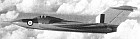
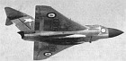
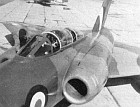
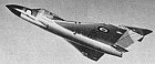
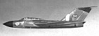
On 20th July, Martin flew the last prototype WT836, for the first time. This machine was distinguished from the other prototypes by having the double transparent hood as fitted to the production machines. THE JAVELIN DESCRIBED Structurally the Javelin was fairly conventional both in construction and in materials. Aluminium alloy was used throughout, except for a small number of steel edge members. No machined skins or frames were incorporated. The fuselage was built in four sub-assemblies, the two largest (the front and the centre fuselage) being permanently joined together during manufacture. The fuselage nose was in fact the radome. On aircraft fitted with British radar, (Mk. 1, 4 and 5), it was removed to give access to the scanner. On aircraft fitted with American radar, (Mk. 2 and 6), the radome was considerably larger and could be pulled forward and hinged to the side to give access to the complete radar installation. In the front fuselage, an inner shell of thick light alloy was sealed at the front and rear by solid frames to form the pressure cabin, which was completed by the windscreen and the electrically operated twin sliding
The engine air intakes were built on to the sides of the front fuselage and enclosed the ducts which connected to the engine compressor casing. Between these ducts and behind the cabin was the servicing bay, containing the gearbox, the starter breeches, the hydraulic panel, the generator control equipment and main electrical distribution panel, besides most of the radio equipment. Access into this very restricted space was gained from underneath. The front-to-centre fuselage joint was made at frame 12, a very heavy structure which incorporated the main wing spar attachment points. The centre fuselage consists basically of the two engine bays at either side of a deep box beam structure, made up of the centre portions of the frames and two longitudinal diaphragms. Rails were fitted in each engine
Each main plane was attached to the fuselage by pin joints at the front and rear spars. The front spar, together with the leading edge ribs and skin formed a torsion box running the complete semi span. Inboard, the wing housed the five fuel tanks, the main wheel units, the Haps, the airbrakes and the magazines. Outboard of these installations were the gun-bays. The outer planes housed the aileron servodynes and provided hinge points for the mass balanced ailerons. The fin was a massive structure, built about two fin posts, attached by pin joints to the centre fuselage box beam, A small fixed portion of the tail plane was built into the top of the fin which provided attachments for the bearing on the tubular spar joining the two halves of the tail plane, The rudder and elevators were conventional all metal structures. The high level of structural efficiency was shown by the fact that on test the standard wing failed at 114°, of the ultimate design load and the fuselage at 118%. Subsequent testing of
The three units of the alighting gear were fitted with Dowty Liquid Spring shock absorbers which were topped up automatically in flight from the aircraft hydraulic system. Dunlop disc brakes, controlled by Maxaret anti-skid units were fitted to the main wheels. The nose wheel castored and was fitted with a self centring device. Because it had no brake, a small spring loaded pad was fitted in the nose wheel housing so that it contacted the tyre and stopped the wheel rotating after it was retracted. The flying control system was a conventional layout. At first elevators, rudder and ailerons were power assisted by hydraulic servodyne units; that is to say that a proportion of the operating load was transmittcd back to the pilot to give feel to the control. It was soon decided lhat this system was unsuitable for the ailerons and a fully powered arrangement was first tested on the fourth prototype and subsequently fitted to all marks. Feel in this instance was provided by a hydraulic centring spring. Although this system was nut designed to be capable of manual operation, a Javelin was in fact landed with manual control after a double pump failure. Power
On the prototypes and on the Mk. 1, the tail plane incidence was altered by an electric motor controlled by a trim switch on top of the control column. On the Mk. 2, and all subsequent marks, this arrangement was replaced by a screw jack driven by twin hydraulic motors to reduce the stick forces at high indicated air speeds. The hydraulic control valve was operated by fore and aft movement of the control column, the elevators acting as anti-balance tabs. Twin feel simulators were included in the control circuit, giving a control resistance proportionate to airspeed and altitude. Trimming took the form of biasing the feel, to decrease the control load in the desired direction. A system to lock the flying controls for parking was operated from the cockpit, the lever being fitted in the throttle box so that only limited engine power could be used when the controls were locked. The hydraulic system was powered by three pumps driven by the auxiliary gear box. One pump supplied the general services such as undercarriage flaps, and air brakes, while the other two served the duplicated systems for the flying control power
The engines were mounted in the centre fuselage, a shaft from each driving an auxiliary gear box mounted in the centre of frame 12. Fuel was carried internally in bag-type tanks, five being in each main plane and two in the front fuselage. From these tanks fuel was transferred by air pressure into two collector tanks in the centre fuselage. These incorporated electric booster pumps and inverted flight valves through which fuel was supplied to the engine. Two drop tanks were carried under the fuselage. A pressure refuelling point in each main wheel bay fed the port and starboard groups of tanks. The electrical system was powered by two 6,000 watt, 24 volt generators, driven by the auxiliary gear box. At one stage in the test programme trouble was experienced with very rapid brush wear at high altitude. This was caused by lack of moisture in the air which at lesser heights acted as a lubricant between the cummutator and the brush. The trouble was cured by fitting very hard brushes developed to work under abnormally dry conditions. The demand on the electrical system was high since, in addition to the normal heating, lighting and instrument services, there were the inverters to supply ax, for the radar, gun firing and flight instruments. The guns
In addition to the A.1 equipment, Gee, A.Y.F., I.L.S, and I.F.F. were fitted. Twin U.H.F. radios were litted under the cabin floor. Both pilot and radar operator had Martin Baker Mk.3 JS ejection seats which operated in conjunction with cartridge powered hood jettison systems. Both occupants wore anti-g suits. The cabin was fully pressurised and air conditioned, heating being provided by jet pipe muffs white a cold air unit and heat exchangers supplied refrigerated air when required. Temperature control was pneumatically
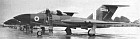
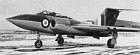
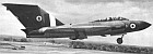
INTO PRODUCTION The official production order for the Javelin came in mid-1953, The Company's factory at Hucclecote was still producing Meteors, so a good many components were sub-contracted out to other members of the Hawker Siddeley Group, in particular Armstrong Whit worths at Coventry, who eventually produced complete aircraft. From the beginning the Javelin was given "super priority production" which was a real help in reducing the airframe production time. Unfortunately the production of bough I-out equipment did not always keep pace and many of the delays were no fault of the parent company. The first Mk.I (XA544) from the line Hew from Hucclecote on 22nd July 1954, the machine, together with the third production machine, appearing at the S.B.A.C. Show at Farnborough that September. In October 1954 the news was released thai a substantial number of Javelins was to be purchased by the U.S.A.F. on an off-shore procurement as a part of the Mutual Defense Aid Program, the sum involved being ?36.8 million. All these aircraft were allocated for use with the R.A.F., following the evaluation by U.S.A.F. pilots Colonels R.Johnson and P.Everest in March 1953. On 21st October Flt. Lt. R. J. Ross, on detachment from the R.A.E., crashed into the Bristol Channel. He was flying solo and, it appears, started
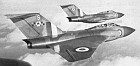
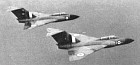
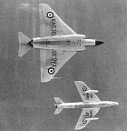
Javelins had their first operational try-out early in 1955 when two of them, XA554 and XA559, took part in "Operation Beware”, the annual air defence exercise. The aircraft were based at R.A.F. Coltishall and were crewed by Sqdn. Ldr. P. Scott, Flt. Lt. Jefferies, Wing Cmdr E. O. Crew, Sqdn. Ldr. J. Walton, Wing Cmdr. "Dicky" Martin and Flt. Lt. Williamson. The aircraft performed well, intercepting and claiming destroyed Canberras some 100 miles off the coast. . . . AND INTO SERVICE On 29th February 1956 the first Javelin was delivered to an operational unit, No. 46 Squadron, based at Odiham and commanded by Wing Cmdr. M. E. White. This Unit's job was to fly as many hours in their Javelins as they could in the shortest possible time, so that operational techniques would be fully worked out and any snags brought to light before the type went into full scale service. The pilots took to the aircraft quickly, finding no difficulty in converting from the Meteor NF.I2 and 14 with which the Squadron
However, another year was to pass before the second squadron was equipped with Javelins. This was No. 141 Squadron, normally based at R.A.F. Coltishall, but at the time temporarily based at R.A.F. Horsham St. Faith, because of runway improvements at Coltishall. The squadron had been previously equipped with Venom N.F.3s, but again had no difficulty in converting to Javelins. The flight commanders had been posted from No. 46 squadron, so that they could pass on the experience they had gained on the type. This re-equipment enabled the R.A.F. to take over the night stand-by (known as "Fabulous") from the Americans. Two aircraft were positioned at the end of the runway with the crews in their seats and the tele-scramble line plugged in. Two more aircraft stood by with crews in readiness. Every hour the crews in the cockpits were changed. Other Javelin Squadrons included the following: Mk. 1—No. 87.
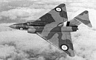
The Javelin Variants F. (AW)Mk. I This had the electrically-operated tail plane. The first 25 production aircraft were used for various development and research purposes. XA552 was fitted with Gyron Juniors D.G.J.10s each of 4500kg static thrust and 40% reheat at sea level. F. (AW) Mk. 2 This had
T. Mk. 3 This was developed to speed operational conversion. The fuselage was lengthened by 4 ft. 10 in. to give room for a second set of controls and to offset the loss of weight from the nose by the omission of the A.I. radar. A small radar ranging set was fitted in its place. Two periscopes, the lenses of which were housed in fairings at each side of the cabin, projected the image for the gunsight in the rear cockpit. Apart from the duplication of the controls and some 'mods' to the fuel system, the T.Mk.3 closely resembled the other marks. The prototype WT841 first flew on 20th August, 1956, and the first production machine on 6th January, 1958. F. (AW) Mk. 4 This was a Mk.1 aircraft with the hydraulically operated all-flying tail. The first production machine flew on 19th October, 1955. F. (AW) Mk. 5 This was a Mk. 4 with an increased fuel capacity wing. The first production aircraft flew on 24th August, 1956. F.(AW) Mk.6 This was a Mk. 2 with an increased fuel capacity wing. The first production machine flew on 15th January, 1957. (C) J. J. Partridge, 1967 |
 All the World's Rotorcraft
|