Aircraft Profile #182. Handley Page Heyford |
|
|
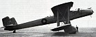
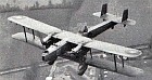
Last of the R.A.F.'s biplane heavy bombers, the Heyford was built to the same 1927 specification (B.19/27) as the Fairey Hendon, the first of the big monoplane bombers, but unlike the latter (whose production was long delayed) it was destined to serve with no less than eleven first-line squadrons. Compared with its predecessors, the Handley Page Hinaidi and the Vickers Virginia, the Heyford was a much cleaner-lined machine and it introduced many original features including a rotating and retractable ventral "dustbin" turret. The Heyford was termed "express bomber" by Handley Page because not only could it carry a considerable load of bombs at high speed, but its arrangements for ground servicing were such that refuelling, re-arming and running adjustments could all be undertaken simultaneously in the shortest possible time. The makers claimed that the machine could be turned round after a 1500km flight in the space of half-an-hour. The arrangement of the fuselage abutting under the surface of the top wing gave the crew a field of vision hitherto unknown in a bomber and this, with the wide field of fire enjoyed by the gunners, combined in the Heyford some of the advantages of a monoplane with the manoeuvrability of
The prototype of the Heyford was the H.P.38 which was designed by Mr. G. R. Volkert (then H.P.'s Chief Designer) and his team to meet Air Ministry Specification B.19/27. Serialled J9130, it had a fabric-covered all-metal airframe and two 550hp Rolls-Royce Kestrel II engines; it first flew in June 1930 at Handley Page's then-new airfield at Radlett, piloted by S/Ldr. T. H. England, the company's chief test pilot. During the summer of 1932 J9130 appeared in the New Types Park at the R.A.F. Display, Hendon, and was also test flown together with the Fairey B.19/27 by pilots of several bomber squadrons, including Nos. 9 and 99. No. 99 considered the H.P. 38 “nice to fly and easy to handle but doubts were expressed concerning the strength of the undercarriage." The doubts were well-founded, for on 10th June, 1932, the H.P.'s undercarriage collapsed at Upper Heyford "for no apparent reason" following a flying demonstration before the Air Member for Supply and Research and the A.O.C.
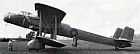
By this time the H.P.38 had been accepted by the Air Ministry and an order placed for a production version known as the H.P.50 (to B.23/32), eventually named Heyford after the bomber station at Upper Heyford, Oxfordshire. The production Mk.I incorporated various improvements. For example, the undercarriage was not only strengthened but now featured deeper spats which covered the lower part of the wheels. Smoother cowlings covered the two 575hp Kestrel IIIS or IIIS-5 engines in the Mk.I, short "ram's horn" exhaust manifolds replaced the long exhausts of the H.P.38 and the underslung radiator beneath each engine was enclosed in a tunnel housing. The fuselage of the Heyford was made in four main sections, joined together by bolts. The front, monocoque, portion was built up of duralumin formers and longerons covered with Alclad; the skin was reinforced by external stringers and the side of the rear half of the
The wings were of duralumin construction with fabric covering. They were equal in span and chord and the top wings were fitted with Handley Page automatic slots. Both sets of wings were in three sections, two outer and one centre section. The lower centre section was deep to accommodate the bombs and was suitably reinforced. The interplane struts were streamlined metal tubes. The tail unit was of the strut-braced monoplane type with twin-balanced rudders and strut-braced fins. It was metal-framed with fabric covering, and the angle of incidence of the tailplane was adjustable in flight. The undercarriage comprised twin single units with wheels (Palmer, with pneumatically-operated brakes) faired into the lower wing. The telescopic oleo struts were hinged to the front interplane strut inside the
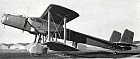
For normal operations the Heyford carried a crew of four comprising (1) pilot; (2) navigator, combining duties of bomb-aimer and front gunner; (3) wireless operator (who in a defensive action doubled as mid-upper gunner); and (4) rear gunner, normally located in the mid-upper gun position, but manning the ventral "dustbin" turret in a defensive action. The crew had quick and unimpeded access to one another, and were provided with intercommunication apparatus. Dual control could be fitted alongside the first pilot's seat, for instructional purposes; the extra set of controls was built up as a complete unit and could be installed within half-an-hour. Entry into the Heyford was gained via a small trap door in the fuselage floor, above the trailing edge of the lower centre section. Steps, fitted on the vee struts which supported the fuselage from the lower wing, rendered access to the interior very easy. Aft of the trapdoor were the rear gunner's cockpit and the retractable "dustbin" turret,
In the rear gunner's compartment there was a tip-up seat on the starboard side, ammunition drums on pegs, points for the electric heating of flying clothing, etc., and so forth. The floor of this compartment was slightly raised, and to the rear was the retractable gun turret, which was entered from the gunner's compartment and lowered by him. When in the "down" position the turret could be rotated through a considerable range. In the front of the gunner's cockpit was a large compartment used for stowing all manner of gear, but with ample gangway space. The floor was corrugated aluminium with wooden strips, for walking on, let into the corrugations. Immediately ahead of the plane of the front spars was the navigation and wireless compartment, with revolving seat and holding table on the port side. Forward of the table, and also on the port side, were shelves on tubular stanchions carrying the wireless equipment, the battery of which was placed on the floor under the set. Separating the wireless compartment from the
A bulkhead with a two-fold door on the starboard side divided the pilot's cockpit from the front gunner's cockpit. This was provided with a "piano stool" type of seat which folded away when not in use. Firing steps were provided at the sides of this compartment so that the gunner could stand up on them and fire in a downward direction. In the
As mentioned earlier, particular attention was given by the Heyford's designers to rapid turn-round between sorties. A bomb loading arrangement was devised which enabled adjustment of the bombs on to the racks, fuse-setting and so forth to be done away from the aircraft, thus reducing the time taken to re-arm. A novel feature of the Heyford was that the bombs, together with racks, and correctly adjusted, were hoisted into the machine as an integral unit, by a special winch in such a manner that when the bomb carrier reached the locating point, the rack was instantly locked; no further adjustments were necessary other than plugging in the electrical leads for the fusing and release of the bombs. Fuelling (oil and petrol) points were provided in a convenient position on either side of the main undercarriage "spats", thus rendering it unnecessary for men to climb over the machine with long hosepipes. Supports for the crank handles of the engine
The high mounting rendered the engines somewhat inaccessible (although this did enable the armourers to reload the bomb bay in perfect safety while the engines were running) but light hook-on ladders helped the mechanics to overcome this difficulty. The ladders (which were stowed inside the fuselage when not in use) could be placed in position in a few seconds, and the side panels of the engine nacelles swung down to form working platforms. The first production Heyford, K3489, made its maiden flight on 21st June, 1933, at Radlett, piloted by Major J. L. Cordes who had now succeeded S/Ldr. England as Handley Page's chief test pilot. This machine was rushed through the shops in order that it might be demonstrated, a few days later, at the S.B.A.C. Display at Hendon, and it did in fact fly at Hendon as programmed. After Service equipment had been installed, the machine underwent official performance tests at Martlesham Heath and was judged by the
Chosen as the first squadron to receive the Heyford was No. 99, appropriately at Upper Heyford; this unit had also been the first to get the Heyford's two immediate lineal predecessors, the Hyderabad and the Hinaidi. Delivery of Heyford Mk.Is to No. 99 began on 14th November, 1933, and re-equipment continued until the following March, by which time 10 (I.E.) and 3 (L.R.) were on strength. A sub-variant of the Heyford Mk.I was the Mk.IA which could only be distinguished from the original version by the absence of the wind-driven generator on the IA. This latter mark had modified engine bearers and a motor-driven generator. As these alterations affected loading weights -important when arranging the bomb load - a suffix to cover them was given to the mark number. Following the Mk.IA came the Mk.II and Mk.III each powered by 640hp Kestrel VIs (de-rated in the case of the Mk.II but operating at full power in the Mk.III) and built to Specifications 28/34 and 27/35 respectively. Both types differed from its predecessor not only in the mark of Kestrel installed but also in having the
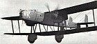
In addition to serving with No.99 Squadron, Heyfords also equipped Nos. 7, 9, 10, 38, 78, 97, 102, 148, 149 and 166 (Bomber) Squadrons. Despite its rather ungainly appearance, the Heyford was well liked by its crews and was very easy to maintain. It had no tricks or vices and such was its manoeuvrability that it was looped on several occasions, including at least one air display when the spectators could hardly believe their eyes! In
By today's standards the Heyford had a comparatively short Service life, being superseded within
One Heyford (K5184, a Mk.III) was loaned to Flight Refuelling Ltd., at Ford, Sussex, for experimental use in June 1939, while two-and-a-half years previously another Heyford (serial unknown) played an important part in some early radar experiments. At that time British scientists were striving to produce, on a scale to fit inside an aircraft, radar equipment to provide results comparable with those of the existing ground installations - which weighed tons and used aerials up to 70m high. By December, 1936, a small receiver was completed and fitted in a Heyford, and when used in conjunction with a ground transmitter, this set gave the first proof that echoes from one aircraft could be received in another. During early 1937 a transmitter was also installed in the Heyford. The emphasis at this time was still on producing equipment to detect other aircraft, but during test flights
(C) Philip J. R. Moyes, 1967
|
 All the World's Rotorcraft
|