Helicopter Flight Theory
1. Helicopter Flight | 2. Flight Controls | 3. Autorotation | 4. Rotor Mechanism

2. Flight Controls
|
Up to this point our discussion has centered on theory of lift and the shape of airfoils best suited to the rotating wings of a helicopter. The second phase of this chapter will deal with the functioning of the flight controls. In a sense, dividing the subject into these two categories parallels the development of the helicopter. The first phase, roughly up until the early 1920's, dealt largely with the problem of perfecting rotors that were efficient enough to permit flight. The next step, through the 1930's and into the 1940's, was the perfection of control systems and mechanisms that would provide the capability for real flight at a fair rate of speed. Our examination of the pilot's control system will be limited to one helicopter configuration, surely the best example, the type which incorporates one main overhead rotor with a small tail rotor at the rear of the fuselage. This classic form, perfected by Igor I.Sikorsky in the United States between 1939 and 1941, remains the predominant type today, although there have been many successful aircraft with various other rotor configurations. It should be noted that the control systems described here are not limited to the single main rotor type but are employed in one form or another in most helicopters, no matter what the rotor configuration. With the Sikorsky configuration, the small tail rotor is intended to offset the torque reaction mentioned in earlier chapters. Torque has no effect while the aircraft is sitting on the ground, since the ship is prevented from rotating by the weight on the landing gear. But once the ship is clear of the ground, the torque effect tries to take over. The practical effect of this — as far as the pilot is concerned — is simply that the tail has a tendency to swing in one direction. To prevent this, a small anti-torque rotor is mounted at the tail, driven by an extension shaft from the engine transmission. This tail rotor is really more like an airplane propeller, since it turns much faster than the main rotor. To keep the helicopter moving straight ahead without turning, the pitch of the tail rotor blades must be just enough exactly to counteract the force of the torque reaction. On most helicopters with a single main rotor, the pitch of the tail rotor is adjusted so that at cruise speed the aircraft is trimmed to fly a straight course. Besides holding the tail end of the fuselage straight against the twisting force of torque, this rear rotor provides control for steering to the right or left, as does the rudder of an airplane. This is accomplished by the pilot's foot pedals, which control the pitch angle of the tail rotor blades: by pressing on the right pedal, the pitch is decreased and the tail swings to the left. Pressing on the left pedal, of course, has the opposite effect: the pitch of the tail rotor is increased so that its thrust now overcomes the torque and tail swings the other way.
The small tail rotor of a helicopter controls the heading of the aircraft by turning the fuselage to the right or left. This is accomplished by the pilot through the movement of foot pedals linked to the tail rotor pitch control, so that by increasing or decreasing pitch he is able to swing the tail to either side. The tail rotor also serves to counteract the torque reaction of the main rotor. The term "control is yaw" is used to describe this effect of the tail rotor — that is, the ability to swing the tail to the right or to the left. Unlike the rudder of an airplane, it isn't necessary for the helicopter to be in forward motion in order for the tail rotor to be effective; as long as the main rotor is turning over the tail rotor will keep spinning, owing to the mechanical drive system that links them together, and the tail control will continue to function. This feature is important in the event of an engine failure or if the engine is slowed deliberately. In this situation the helicopter descends with the main rotor free-wheeling in autorotation. The fact that the tail rotor will keep turning with the power cut off means that directional (yawing) conrol can be maintained, and the pilot will still be able to steer the aircraft as it descends. Another primary control used to fly a helicopter is the collective pitch stick, located to the left of the pilot's seat and mounted on a pivot so the pilot can ease it up and down with his left hand. By means of this control the pilot can increase or decrease the pitch angle of all the blades in the main rotor, equally and simultaneously. For example, to make the aircraft rise, he pulls up on the collective stick — this is called "pulling in pitch" — and the effect is to increase the pitch angle of the blades and thus, to increase the lift. However, as the blades meet the air at a greater angle of attack, * the drag on the rotor will increase as well as the lift. Therefore, to maintain a constant rotational speed it is necessary to increase the power by speeding up the engine as the stick is raised.
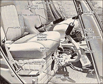
A close-up view of the cockpit of the Hughes Model 269A show's both seats and dual -flight controls. A cyclic control stick, similar to an airplane stick, is located in front of each seat. The collective pitch lever is between the two seats; moving it up or down increases or decreases the pitch angle of all three rotor blades simultaneously. A twist-type throttle for the engine is mounted on the collective lever. All flight controls are shown except the rudder pedals, located on the -floor in front of each seat. The 269A, a light two-seater, is one of the smallest helicopters in service. This brings us to yet another control, the throttle for the engine. Since the pilot already has both hands and feet occupied, the problem is solved by providing a rotating handle (similar to the twist grip found on a motorcycle) mounted directly on the collective stick. As the pilot pulls in pitch by raising the stick with his left hand he also twists the throttle slightly to speed up the engine. We can see how this control is used by following the actual motions that the pilot makes during take-off. First, he will bring the rotor up to the correct speed by opening the twist-grip throttle. He then eases up on the collective pitch stick, increasing the bite of the main blades while simultaneously adjusting the power of the engine to maintain the rotor speed. When the lift force developed by the rotor becomes greater than the weight of the aircraft, the landing gear will begin to clear the ground. In a condition of hovering flight the lift exactly equals the weight, and the pilot can then raise or lower the helicopter by increasing or decreasing his collective pitch. The technique of using the left hand to operate both the throttle and the collective stick is one of the problems peculiar to flying a helicopter. Coordination of the throttle and the collective pitch is vital in maintaining the speed of the rotor at the all-important correct number of revolutions per minute. To make the task easier for the pilot, most of today's helicopters employ a mechanical linkage in the collective control which automatically adds throttle as the pitch is increased. However, with many helicopters the pilot still has the chore of making constant small corrections in spite of the action of this linkage.
To rise vertically, the pilot raises the collective pitch stick with his left hand. This increases the pitch angle of all rotor blades simultaneously, thus increasing the over-all lift. The last primary flight control is the cyclic control stick. The cyclic stick is mounted vertically from the cockpit floor, between the pilot's legs, in the same position as the control stick of an airplane, which it so greatly resembles. Like the control stick of an airplane, it can be moved slightly in any direction from the vertical. With this control the pilot can move the helicopter in any direction horizontally - that is, for flying straight ahead, backing up, and for moving to either side.
These three illustrations show the effect of the pilot's cyclic control stick; the direction of -flight follows the direction in which the stick is moved. When the stick is moved to the front or rear, or to either side, the "disc of rotation" is inclined in that direction. When the cyclic stick is moved fore or aft, to either side, or in any combination of these, the whole whirling rotor system-termed the "disc of rotation" — will be tilted in the same direction and the movement of the helicopter will be in this direction. This is accomplished by changing the pitch angle — and thus the angle of attack—of each blade in cycles, from a maximum to a minimum position, as the blade sweeps through a complete revolution. The way this works is illustrated by what happens when the rotor disc is tilted forward, to move the helicopter into forward flight. The pilot pushes his control stick forward slightly; the result is that the blade which happens to be at the rear of the disc has its pitch increased by the control linkage, while the blade which happens to be moving around at the front has its pitch decreased. Since each blade is attached to the hub by a hinge which allows it to flap up and down slightly as it turns (here we are describing a standard articulated rotor), the blade at the rear will rise upward and then, as it moves around to the front, it will ride at a lower than normal position. The over-all effect is that the rotor disc — actually the path the blades take describes the shape of a shallow cone rather than a disc — will be inclined forward so that its lift is no longer straight up but is now pulling slightly forward as well. In the same way, the cyclic stick can be used to incline the rotor to move the helicopter in other directions. An important function of the cyclic control system is that it allows the pilot to correct for dissymmetry of lift. This phenomenon refers to the unequal lifting forces created as the helicopter speeds up and moves forward through the air that, unless corrected, can cause the aircraft to roll to one side. To understand this, it is helpful to visualize the position of each blade in relation to the airflow coming from the front as it sweeps through the full 360-degree circle of rotation. Each blade can be thought of as advancing when it sweeps forward against the airflow from the front, and retreating when it swings past the straight-ahead position and begins to move to the rear on the other side of the circle. Since the blades obtain lift from both the airflow induced by their rotation and from the flow from the front, it is not surprising that the advancing blade, which is meeting the flow from the front head on, will create more lift than the retreating blade. Because of this, the advancing blade will tend to flap up while the retreating blade, which is "running away" from the airflow from the front, will flap down. The effect is that the rising blade is actually decreasing its angle of attack, since the movement of the air against the blade is no longer horizontal but is now slightly downward—owing to the blade moving upward. On the other side of the rotor the situation is reversed; there the blade is actually increasing its angle of attack since it is "diving down" against the airflow. This flapping effect is quite beneficial because it results in an equalization of the angle of attack — and therefore the lift force — created on the right and left sides of the rotor disc, and eliminates the tendency for the helicopter to roll to one side. However, there is an undesirable result from this flapping action which can be overcome through use of the cyclic pitch control. As the advancing blade flaps upward it reaches its highest flapped position directly in front, one-quarter of a revolution from the point where the increased lift began to take effect. Conversely, the retreating blade reaches its lowest flapped position directly to the rear, over the tail of the helicopter. Therefore the tendency of the aircraft to roll, eliminated by the flapping of the blades, is now changed to a tendency for the rotor disc to pitch to the rear and thus for the helicopter to climb as it goes into forward flight. This might seem to call for still more complications in the control system, but fortunately this is not the case. To start the ship moving forward initially, the pilot had pushed his cyclic stick forward. To overcome the climbing tendency he simply pushes the stick still farther forward, responding naturally to the nose-up position, and the rotor disc remains in the desired attitude. One of the important characteristics of lift dissymmetry is that it becomes much worse as the helicopter speeds up and flies faster. Since the lift on the blades on the advancing side cannot be permitted to exceed the lift on the retreating side, this factor tends to limit the top speed at which the fastest helicopters (with conventional rotor systems) can fly; for even the largest and most powerfully-engined of helicopters, at speeds just above 200 miles per hour the lifting and propelling characteristics of the rotor are affected, and a phenomenon termed "blade stall" is encountered.* With these primary controls — pedals for steering, the collective pitch stick (with the twist throttle), and the cyclic stick — the pilot can move his ship in any direction, turning it around on the axis of the main rotor, moving it up, down, forward, to the rear, and sideways. Obviously, a helicopter pilot can be very busy indeed. Each hand and both feet may be at work at the same time, and the pilot's left hand will have two jobs to do simultaneously, pulling up on the pitch stick while feeding in power with the throttle. Added to this is the fact that most copters do not possess the inherent stability found in airplanes, being in this respect more comparable to an automobile than an airplane; you can't let go of the controls for more than a few seconds at a time. But these seemingly complicated motions are easily absorbed, and a natural pattern of action and reaction is quickly established by most student pilots. C.Gablehouse "Helicopters and Autogiros", 1969 |
1. Helicopter Flight | 2. Flight Controls | 3. Autorotation | 4. Rotor Mechanism