Flying Bell 407
From Fly! II simulator's documentation by Terminal Reality Inc.
It might be interesting to read how to fly a helicopter. Just ignore all those "Press Ctrl-PgDn" etc.
1. Rotary-Wing Aerodynamics | 2. Cockpit Tour | 3. Let's Fly ! | 4. Getting Back Down

2. Cockpit Tour
|
COCKPIT TOUR Right off the bat, you'll notice something different. All the airplanes you've flown have been commanded from the left seat. The Bell 407, like most helicopters, is flown from the right. This is, at least partly, a hangover from the bad old days when helicopters were even more unstable than they are now. You'll notice that I didn't say "less stable;" even the nicest current light helicopters are, at best, neutrally stable. Where an airplane, if disturbed from trimmed flight, will attempt to return to the trimmed condition, a helicopter will just go off in the new direction after the disturbance. Most helicopters are, in fact, unstable—they don't even need a disturbance to want to go off in a new direction, but are constantly trying to do so on their own. What this means is that they have to be flown every second. For all practical purposes, you can never let go of the cyclic stick, which you hold in your right hand. The collective, on (and in!) the other hand, is a bit less critical—when you're not actively maneuvering, you can let go of it for a few seconds at a time. Therefore, it makes sense to put the pilot all the way over on the right, so that he or she can get to necessary controls with the left hand. Not that you want to stay away from the collective all that long, either—in the event of an engine failure, you need to lower the collective right now to avoid excessive loss of rotor RPM. CONTROLS As mentioned before, your primary flight control is the cyclic, which isn't depicted in Fly! II, the anti-torque pedals, and the collective. The latter two are visible in the view below the main instrument panel, which you can see by tapping [Ctrl+down arrow]. WHAT ABOUT POWER? If you have your right hand on the cyclic, your left hand on the collective, and your feet on the antitorque pedals, how are you going to control the throttle? Well, in a modern turbine helicopter like the 407, the answer is simple: you don't! This wasn't the case in older piston-powered helicopters such as the 407's ancestor, the Bell 47 (the "mosquito carrying a flashlight bulb" you see in the opening credits for M*A*S*H, for example). In those machines, the throttle was controlled by a motorcycle-style twist grip on the collective, which is why such helicopters (as well as the iron men and women who flew them) were called "throttle twisters." Helicopters of this era had mechanical linkages between the collective itself and the throttle, called "correlators," whose purpose was to minimize the amount of throttle-twisting required; depending on the model of helicopter, the flight conditions (altitude, temperature, gross weight, etc.) these worked after a fashion—but there was still plenty of throttle twisting required. With the advent of gas turbine power, the helicopter pilot's workload was suddenly reduced: these engines have automatic governors or regulators, and when working properly throttle management becomes almost a "set it and forget it" evolution. In extreme conditions, however, or when maneuvering hard, it's still possible to "get ahead" of these governors, leading to engine overtemperatures or RPM "sags." The latest technology, which is installed on the 407, is FADEC—Full Authority Digital Engine Control. When this is operating correctly, there's no direct mechanical connection between the collective and its twist grip throttle and the engine. Instead, an electronic computer (the Electronic Control Unit, or ECU) measures a whole raft of parameters including engine and rotor RPM, temperature, altitude, collective position, etc. and provides not only virtually instantaneous power response with no overshoots, but protection against overtemperature or overspeed. It also makes engine startup a fully automatic sequence. In normal flight, the twist-grip throttle is simply positioned to its "FLY" detent and left there. In case of FADEC failure, the system reverts to manual mode and the engine can be controlled by the twist throttle.
Let's take a quick look at the overhead panel, which controls some important functions, and then move on to the main instrument panel. Tap on [Ctrl+up arrow] to see the overhead panel.
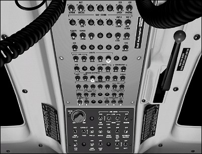
That big red handle at the aft end is the rotor brake, which is used only during engine shutdown, and then only after the rotor has slowed down below 40% RPM. Make sure it's released before engine start—and when you shut the helicopter down, make sure the blades are parked at a 45-degree angle to the fuselage. This is to avoid heat damage to the fiberglass blade if it were parked right above the hot exhaust duct. Circuit breakers protect all the helicopter's electrical services. Notice the two small toggle switches at the front of the circuit breaker panel. These control a couple of fuel pumps, and the left one is hot-wired to the helicopter battery. This means that if you don't make a point of shutting it off during your shutdown procedure, you'll come back to a dead batter next time. NOTE—in the actual helicopter, the overhead panel is mounted in the ceiling, and all switches are moved forward to turn them on. When viewed on your computer screen, this means that switch handles move DOWN to turn on, UP to turn off. This applies only to the overhead panel; switches on the main panel or control pedestal move in the normal "UP=ON" direction. Ahead of the circuit breaker area is the main switch panel, and the most important switches are in the forward (bottom) row. From left to right, they control the hydraulic control boost ("power steering," if you like), the anticollision light, the inertial particle separator if installed (this keeps foreign matter, such as snow, dust, or loose grass out of the engine intake, but costs a bit of power), the generator, and the battery master. The battery switch is turned on before startup, and turned off last after shutdown; turn it off prematurely, and you'll lose such things as all the engine instruments while the engine is still winding down. Now hit [Ctrl+down arrow] and we'll look around the main instrument panel. MAIN INSTRUMENT PANEL
Across the top of the panel are three rows of caution and warning lights. Most of the yellow ones are of the "land as soon as practical" variety, although "fuel low" and any of the engine or transmission chip lights (meaning that metal chips have been detected in the oil) qualify for the more immediate "land as soon as possible." So do the red lights; obviously, if you get the "engine out" light, you don't have much choice. The one you really don't want to see is the red RPM light, meaning that rotor RPM is dangerously low, and you're approaching blade stall, and this light is reinforced by a loud horn. Your reaction should be to get the collective down now, and establish a steady autorotation; then, and only then, sort out the problem if there's sufficient time and altitude. The large push-button to the right of the caution and warning lights tests them all simultaneously. The main instrument panel itself has three rows of large flight instruments at the right, and two rows of smaller engine instruments at the left. The first two instruments down from the top in the leftmost row of large instruments are the two most important ones for flight. FLIGHT INSTRUMENTS Right at the top, in the center of the panel, is the airspeed indicator. You'll notice that it reads quite a bit lower than those you'd find in an airplane. It also has not one, but two redlines. The highest, at 140 KIAS, is the absolute limit for the helicopter, but it only applies at low altitudes. At higher altitudes and/or temperatures, lower maximum speed limits apply; they're placarded in the cockpit. The other (striped) redline, at 100 knots, is applicable under a number of conditions, including flight with any (or all) cabin doors removed, flight at high gross weights, and autorotations. If the placard maximum speed for a given altitude is lower than 100 KIAS, the lower speed applies. Not shown is another limitation. Due to the possibility of interference between the antitorque rotor and the tail boom if full left pedal is applied at high forward speeds, an automatic device restricts pedal travel at higher airspeeds. If this system is disabled, maximum speed is restricted to 60 KIAS. Just below the airspeed indicator is an even more important instrument: the dual tachometer. Remember, what's most important in a helicopter is the airspeed over the blades; obviously, that's directly related to their RPM. On the dual tachometer, the inner needle, labeled Np (for Powerplant) shows the RPM of the engine's output shaft; the outer needle, labeled Nr (for Rotor) shows the RPM of the main rotor. Both are expressed in percent of maximum; at 100%, the rotor is turning at 413 RPM (and the engine output shaft at just over 6000). In normal operation, the two needles will be "married" at 100% RPM. In fact, you'll notice that the allowable range for Np is extremely narrow—basically, 100% RPM, period. The allowable range for the rotor is somewhat wide (from 85% to 107% RPM), but you'll see that only under very abnormal circumstances, and only when the transmission and rotor system are decoupled from the engine for some reason (for example, if the engine has failed). In this case, you'll see split needles on the tach. To the right of these instruments are standard flight instruments (artificial horizon, HSI, altimeter, and VSI). For our purposes, we can consider these relatively unimportant: since the 407 is not certificated for instrument flight, and since it's typically flown at low altitudes, it's generally operated primarily by the time-honored practice of looking out the windows. In fact, helicopters in general, and light ones like the 407 in particular, are one of the last bastions of true "seat of the pants" VFR flying. Below the flight instruments is the indicator for the ADF. You can select navigation information from either the GPS or the VOR receiver to be displayed on the HSI by using the push-button switch at the right edge of the instrument panel. ENGINE INSTRUMENTS The engine instruments are arranged in two vertical rows just to the left of the flight instruments, with the three most important ones right next to the airspeed indicator and dual tachometer. At the top is the torquemeter, which indicates directly how much power is being supplied to the rotor. This is your primary power setting instrument, and is affected directly by movement of the collective. Next down is MGT, which stands for Measured Gas Temperature—the temperature of the stream of hot gas in the engine. While the torquemeter is your power setting instrument, MGT is your power limiting instrument: at higher temperatures and/or altitudes, you may reach limiting engine temperature before you have obtained all the torque you might like. In this case, you'll just have to be content with what power (torque) you can obtain. You'll notice a couple of red markings beyond the redline. The first, at 843 degrees, is a start limit; you should abort an engine start if MGT goes above this mark for more than a couple of seconds. The second, at 905 degrees, is an absolute limit beyond which any engine operation will be recorded immediately as an exceedance. Below this, and the third of the "really important engine instruments," is Ng—the RPM of the gas generator portion of the engine. Like rotor RPM, this is calibrated in per cent (if for no other reason than that the actual number—over 50,000 RPM at high power—would make the gauge pretty crowded). In normal operation, with the FADEC operating properly, this can be pretty well ignored. If FADEC fails, however, you should match the setting on the twist-grip throttle to the indicated Ng; markings are engraved on its bezel ring for the purpose.
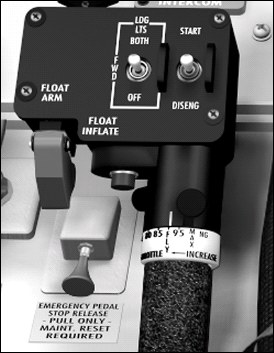
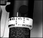
All three of these instruments have LCD displays for highly exact readings. In addition, all of them constantly monitor their values. If any value is exceeded, it will begin to flash as a warning to the pilot to reduce power immediately; the "check instr" light at the top of the panel will also flash. After a few seconds of flashing (it varies depending on the parameter), flashing will cease and the date, duration, and value of the exceedance will be recorded. The digital display in the instrument will display the letter "E" and the value of the exceedance for 11 seconds. The "check instr" annunciator will remain on until you push the "instr chk" button just below it. You can tell that there's been an exceedance (which, in the real world, would be reported to maintenance) when you first apply electrical power before startup: the affected gauge will once again display the E and exceedance value, and won't indicate correctly until you acknowledge it by pressing the "instr chk" button. In the real world, this information remains stored in the helicopter, and displayed every time it's powered up, until cleared by maintenance using a laptop computer. The remaining engine instruments monitor parameters such as oil pressure and temperature for both the engine and transmission, fuel quantity and pressure, and generator output. The top left instrument is a digital clock, which also displays outside air temperature and system voltage (selected by the red button at the top). Don't try a battery start unless you see at least 24 volts, or a hot start is likely. There are also a few important switches and buttons on the main panel. At the bottom right, with a red guard to secure it in the ON position inflight, is the master fuel valve. Normally, it's turned off after shutdown (which also cuts the left and right fuel pumps), but in an emergency (such as complete loss of engine control), it provides a last-ditch way to shut down the engine. To its left is the FADEC switch; successive pushes change from FADEC to manual mode, annunciated on the switch. This is normally used only to deal with FADEC malfunctions. At the extreme right edge are two more switch/annunciators; one, mentioned above, switches the HSI display from the Nav 1 receiver to the GPS; the other overrides the high-airspeed left antitorque pedal block (for example, to restore full pedal travel at low speeds if the block fails to disengage). At the top, just below the red RPM warning light, is a button to mute the various warning horns. Finally, tap once again on [Ctrl+down arrow] to take a closer look at the collective. You'll notice the twist-grip throttle, with its calibrations for approximate Ng when operating in manual (non-FADEC) mode. Next to these markings is a small, round silver button. This is the idle stop release. Once the engine is running, the twist grip can't be rolled off to the "stop engine" position unless this button is pushed and held. There are two switches on the head of the collective lever. The left one allows you to turn the landing lights on and off without moving your hand away from the collective. The right one, spring-loaded to its center OFF position, controls the starter. For a normal FADEC start, it only has to be held momentarily to the START position; the starter will then remain engaged, shutting off automatically at the conclusion of the start sequence. To manually disengage the starter, hold the switch briefly in the DISENGAGE position. |
1. Rotary-Wing Aerodynamics | 2. Cockpit Tour | 3. Let's Fly ! | 4. Getting Back Down
![]()
![]()