| Fairey "Rotodyne" 1953 |  |
 |
|
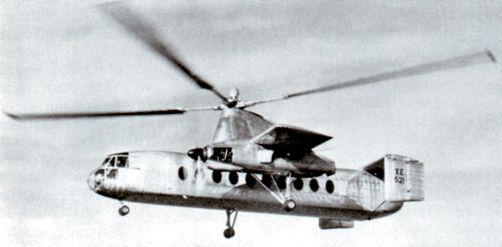
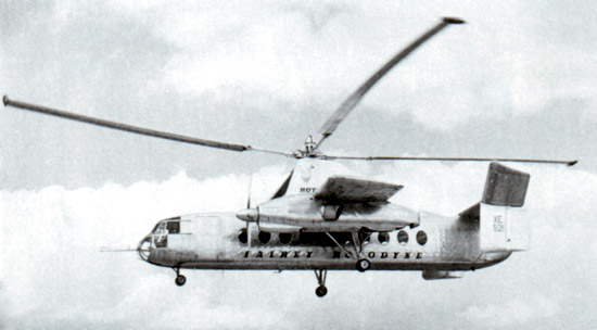
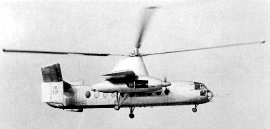
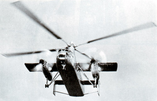
| Fairey "Rotodyne" 1953 | |
|
|
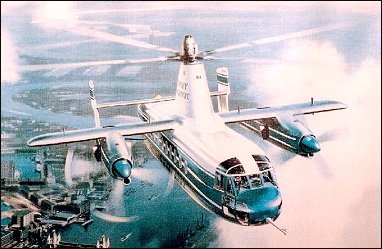
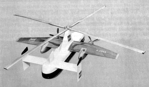
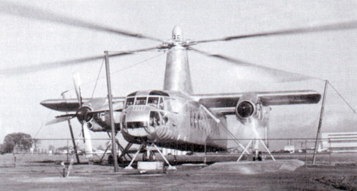
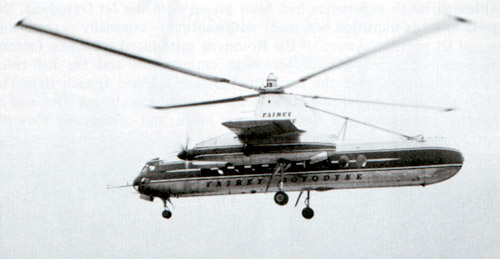
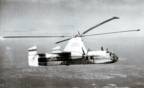
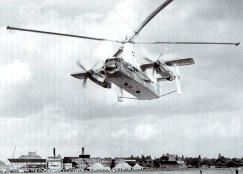
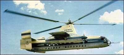
The Rotodyne was a compound aircraft with wings, tractor engines and a tip-driven rotor system. Unfortunately, it was use of the tip jets at and near the airport that was the problem. The Rotodyne put out a painful 106 decibels of shrieking noise. Much work was done on silencers, but it was never reduced to the 96 decibels that the authorities demanded. Budgetary problems of the time saw the RAF and British Army withdraw their interest and the Rotodyne became a wholly civil project. Fairey talked up expressions of interest from BEA in the UK, New York Airways and the US Army, but the crucial launch order never came. British government policy to rationalize the industry saw the end of the Rotodyne and Fairey as an airframe maker in 1962. Jim Winchester "The World's Worst Aircraft", 2005
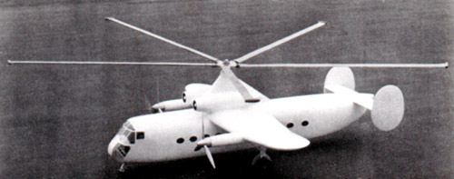
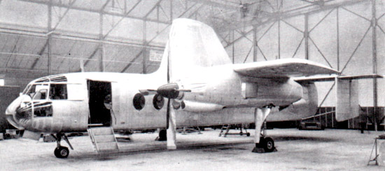
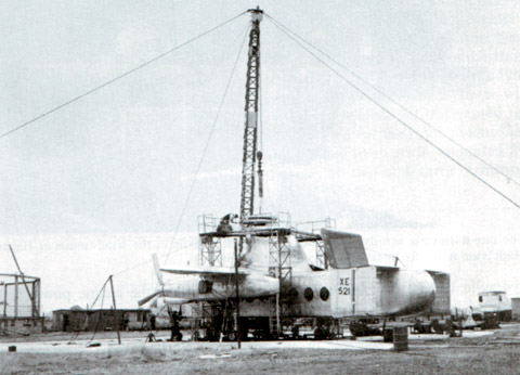
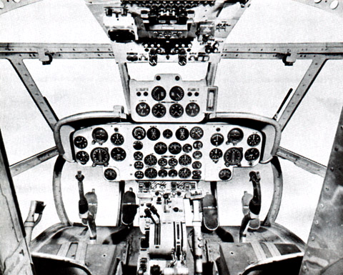
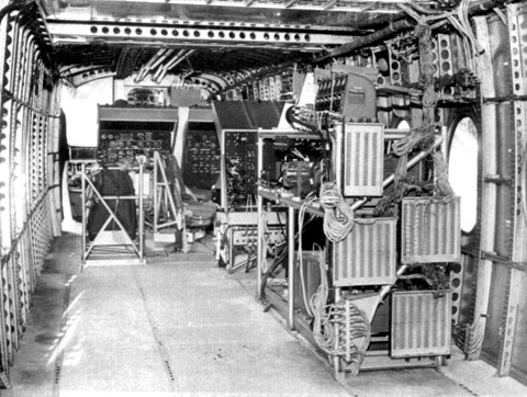
The concept of a vertical take-off airliner has captured the imagination of designers and airlines virtually since passengers were first taken aloft in a balloon, almost exactly 200 years ago. With the concept of the convertible helicopter proved on a small scale with the Jet Gyrodyne, the proposal put forward by Dr. J.A.J. Bennett and Captain A.G. Forsyth in 1947 for a large compound helicopter looked viable, and various designs were considered. In December 1951 British European Airways issued a specification for a 30-40 seat passenger aircraft for short/ medium-haul routes and Fairey submitted a proposal along with other manufacturers; the layout corresponded roughly to Fairey's ideas and in 1953 the company received a Ministry of Supply research contract for a prototype. Test rigs were established at White Waltham and Boscombe Down, where an elaborate installation eventually comprised the rotor assembly, both power-plants, stub wings, etc., with all controls in a hut where the aircraft's nose would have been. Extensive testing was carried out while the prototype was under construction, and the Fairey Rotodyne made its first flight as a helicopter on 6 November 1957; it was not until April 1958 that the first transition to normal flight was made. Basic layout of the Rotodyne was a square-section fuselage with untapered stub wings on which were mounted two Eland turboprops for forward propulsion. The main wheels of the tricycle landing gear retracted forwards into the nacelles, and the nosewheel forwards below the cockpit. Twin fins and rudders, later joined by a central fin, were mounted on an untapered tailplane set on top of the rear fuselage. A large four-bladed rotor for vertical take-off and landing was driven by tip jets which received compressed air from the Eland engines via a compressor; each engine fed air to two opposing rotor blades to ensure that, in the event of an engine failure, there would be enough pressure in the remaining engine to keep two tip jets burning. Following its success in establishing a speed record with the Gyrodyne, Fairey decided that the Rotodyne's performance would enable it to repeat the feat, and on 5 January 1959 it set a record in the convertiplane class with an average speed of 307.2km/h over a 100km closed circuit; this record stood until October 1961, when the Russians beat it with the Kamov Ka-22. The Rotodyne's future looked bright; during 1958 the Kaman Aircraft Corporation secured a licensing agreement for sales and service in the USA with a possibility of manufacture there. Okanagan Helicopters of Vancouver was interested in three and Japan Air Lines was considering the type for domestic routes. However, the biggest potential customer was New York Airways, which joined with Kaman in a letter of intent for five, plus options on 10, for delivery in 1964. These were to be the larger 54/65-seat versions with Rolls-Royce Tynes. Fairey needed up to GBP 10 million to develop this version and was offered 50% of this by the government if BEA would place a firm order. The government contribution was to be a loan, repayable by a sales levy. In 1960 Fairey merged with Westland and although initially the Rotodyne project looked secure, it was not. In April 1960 Okanagan cancelled its order because of the long delivery dates, and five months later New York Airways expressed concern over the delay in production plans. Westland was then involved in taking over Bristol's helicopter programme as well as with other work in hand. This, together with the ever-increasing weight of the Rotodyne, which reached a stage where the Eland could no longer be developed and the Tyne could not be afforded, led to withdrawal of government support, and the project was cancelled in February 1962. D.Donald "The Complete Encyclopedia of World Aircraft", 1997 By 1956, when most of the details of the Rotodyne had been worked out and descriptions had been published in the technical press and elsewhere, it was generally considered in knowledgeable circles that this was an aircraft with a potential which could bring striking new developments for short/mediumhaul air transport. Here was a compound, or convertible, helicopter of a commercially practical size, even in its prototype form, which would be able to fly as a helicopter to and from small spaces and as an aeroplane-cum-autogyro at reasonably high speeds over inter-city stages. But it was not to be. After the expenditure of considerable sums of money and an immense amount of technical effort, coupled with some four years of test flying, the project was cancelled on 26 February, 1962. On that date the British Minister of Aviation, Mr Peter Thorneycroft, said that, because of the costs involved, it was necessary to 'forego the operational advantages' offered by the military version, and that British European Airways, then its only potential British civil operator, had regretfully concluded that 'the commercial prospects on their routes were not sufficiently assured to justify the heavy liabilities involved' in placing a production order. In the absence of any firm order, Westland Aircraft - who, in the massive merger operations of the period, had taken over Fairey Aviation's aircraft and helicopter activities two years before � did not feel justified in proceeding with the project. By then most of the technical and handling problems had been solved, or were in process of solution, and the production version was a known quantity with a guarantee-able performance. The progress towards the definitive version had been too long delayed and potential world customers had lost confidence and interest. Maybe if more money had been available over a shorter time-scale the story could have been a different one. As it was, something of the order of GBP11 million was spent during the nine years or so following the placing of the original research contract in July 1953. During the final three years of the period, however, financial support had been uncertain and the project suffered from continuing political and other indecisions which made costly forward planning impossible. As will have been gathered from the description of the Jet Gyrodyne - the research aircraft used for the development of many of the principles involved - the Rotodyne was, in effect, an extrapolation of the original Gyrodyne principle - with a power-driven rotor for vertical flight, propellers for propulsion and an autorotating rotor for cruising flight. The main difference, apart from the tip-jet drive for the rotor, was the use of a sizeable wing area to share the lift with the autorotating rotor. As explained in the Gyrodyne sections, the limitations of the helicopter, in terms of speed, was the stalling of the retreating blade and consequent vibration;as forward speed increased, the true airspeed of the retreating blade fell. A palliative was to reduce the loading on the rotor and, therefore, the stalling speed of the retreating blade. In the Rotodyne the loading was reduced by sharing about 50 per cent of the lift at cruising speed with the wing and, as with its predecessors, using propellers instead of the rotor for forward propulsion. Not only was a 'tilted' rotor very inefficient when used for propulsion, but it required more incidence and was obviously, therefore, more heavily loaded and liable to earlier stall of the retreating blade. The tip-jet drive was adopted so as to simplify the considerable transmission problems with a large rotor; gearing capable of taking 6,000hp would have been required with the Rotodyne. The use of tip-jets also eliminated torque and the need for drag hinges for the blades. To provide compressed air for the jets the two 2,800shp Napier Eland N.E1.7s operated as dual-purpose powerplants - acting either as normal propeller-turbines or as pressure-generators according to requirements. They were virtually normal Elands up to the rear of the turbine casing, where there was a nine-stage axial compressor driven by the power turbine through an hydraulic clutch. For take-off and landing most of the engine power was absorbed by the compressor, which delivered air to the internal duct system of the rotor. The small amount of remaining power of the engines went to the propellers for yaw control. In cruising flight all the power went to the propellers, with the rotor autorotating. Each engine fed air to two opposing blades so that, in the case of failure of one engine, there would be adequate pressure to keep two jets burning efficiently and giving maximum thrust. In its original form the control system followed, in basic principle, that of the Jet Gyrodyne, with direct roll and fore-and-aft control through the cyclic pitch-change of the rotor-blades; with a trimming 'elevator' used to select fuselage attitude (and consequently wing lift) in cruising flight; and with yaw control by differential propeller-pitch at low speeds or when hovering, and by rudders at higher cruise speeds. Fairly early in the test programme it was found that the fore-and-aft attitude control, using the separate functions of cyclic rotor-control and elevator trim, produced some difficulties. The solution was to link the elevator to the longitudinal cyclic control for both slow and high-speed flight and to disconnect the cyclic control when cruising. Later, when it was found that the economical cruising speed was more like 273km/h than the originally planned 209km/h, it was found that, at higher speeds, the wing was doing too much work and the rotor too little, so that the blades were flapping and the control margins were inadequate. The wing, originally set at an incidence of 4�, was re-set at 0� and fitted with ailerons, the operation of which was linked directly to the cyclic lateral control of the rotor. The outward-sloping upper fins were also moved to the vertical so as to reduce the rolling tendency with yaw. These changes produced a normal 'aeroplane-type' rolling control for the pilot, and the situation was further improved later by the fitting of a third upper fin. The proposal for a large compound helicopter originated in a 1947 study, with associated 1949 patent, by Dr J. A. J. Bennett and Capt A. G. Forsyth. Before the final version was decided upon and detail design work started, the project went through many different though broadly similar forms. Apart from an early research project consisting of a 900kg gross pressure-jet helicopter, one of the first was a 15-seater, with two Alvis Leonides engines in wing pods, which was proposed in 1949. By 1950 larger projects were being considered, all incorporating tip-jet units. Various powerplant combinations were proposed for these, which were the first to be given the name Rotodyne. One such installation involved the use of three Rolls-Royce Darts with pressure bleeds for the jets. Another, with a five-blade rotor, featured two projected de Havilland H.7 gas-turbines mounted on the rotor pylon; these drove auxiliary compressors which were coupled to two wing-mounted free turbines driving propellers. Earlier, the use of two and three Armstrong Siddeley Mamba propeller-turbines had been proposed. The first mention of the project and of the name Rotodyne was made in March 1951 by the Ministry of Civil Aviation's Interdepartmental Helicopter Committee in its initial report. No details were given, but it was reported to have two propeller-turbines and tip-jets, to have a cruising speed of 217km/h and capacity for 23 passengers. This was probably the Mamba-engined project. Confirmation of the need for such an aircraft was provided by the British European Airways specification of December 1951 for a short/medium-haul 'BEAline Bus'. Five manufacturers submitted projects to meet this earlier specification for a 30/40-passenger aircraft. Fairey's original proposal again incorporated the projected D.H. powerplants. These were in two underwing nacelles, in each of which was located a main gas-turbine driving an auxiliary compressor and, mounted in tandem, a second turbine driving a constant-speed propeller through a reduction gear. Air for this turbine was tapped from the auxiliary compressor of the main engine. The rotor was four-bladed, with pressure-jet units at the tips. The final version, with two Elands driving propellers and/or auxiliary compressors, was outlined in 1953 and formed the subject of a Ministry of Supply research contract. This became the definitive prototype, leading later, without very fundamental changes, to the proposed production Rotodyne FA-1, or Type Z, of 1959-60, with planned seating for up to 70 passengers. For this, XH249 (F.9430), the Elands could not provide the power required, so two 5,250shp Rolls-Royce Tyne propeller-turbines were envisaged. But in hot/high conditions, even this power would have been only just adequate in the engine-failure on take-off case, and Rolls-Royce suggested separate air-producing engines to supply the tip-jets. The proposed solution was to install, at the rear of each nacelle, an RB.176 in which a lightweight gas-turbine drove an auxiliary compressor. By this use of separate propulsion and lift power there would be a considerable increase in weight, but the arrangement gave worthwhile gains in off-design conditions. The Fairey pressure-jet unit for the prototype consisted of a circular-section flame-tube fed by three air pipes and one fuel pipe. This was faired within a streamlined nacelle and terminated in a simple propulsive nozzle. The BEA type specification for the production Rotodyne stipulated an initial climb, at zero forward speed and maximum weight, of not less than 1823m/min, and a noise level, at a distance of 183m, of not more than 96 decibels. With the power planned for the production Rotodyne the noise level for the existing tip-jets would have been about 113 db. To achieve the necessary 17-db reduction in noise level a complete redesign of the pressure-jet was planned. This would have been in two-dimensional form, occupying the last 1.2 metres of each blade, with nine circular flame-tubes in a combustion chamber submerged within the blade profile. Research by Fairey on the development of tip-jet propulsion for rotor blades had started as early as 1947 and static tests of a combustion chamber were soon in progress at Hayes alongside work on ramjets and pulsejets. By the end of 1950 it had become obvious that the pressure-jet principle was the only one suitable for large helicopters - if only because of its lower fuel consumption. New test facilities were set up at White Waltham in 1951 for the development of the tip-jets. These consisted initially of a test stand and a rotating rig for chamber-spinning tests. A Rolls-Royce Dart engine, with air tapped from the combustion chambers, was used as a compressor plant for the rig; two other Dart compressor plants were used for the air supply to the rotating stand. On this, a balanced single-bladed rotor, with hingeless hub, was used to investigate tip-jet light-up, regulation, performance, cooling and loads during rotation. Prior to installation on the Jet Gyrodyne, a complete rotor, including hub, blades, jet units and controls, was installed. By the end of 1953 the chamber and rotor had been developed, and the Jet Gyrodyne, as already recorded, flew untethered for the first time in January 1954. These rigs were also used for the development of the chamber and rotor for the Ultra-light helicopter, but new rigs were completed at White Waltham in September 1955 and April 1956 for the Rotodyne. In addition to these, a completely realistic test installation was set up in 1956-57 at Boscombe Down. This consisted initially of one Eland powerplant, with propeller, and auxiliary compressor feeding a two-bladed rotor, with flying and engine controls exactly as on the aircraft itself. The controls were in a hut placed dimensionally as in the Rotodyne and 'flying' started in April 1957. Later the rig was completed with two Elands and the two additional rotor blades in place of the original balancing 'dummies'. Included in the rig were most of the critical or untried features of the Rotodyne, so it was extremely useful, if not invaluable, in ensuring safety during the earlier flight trials. Meanwhile, at the Hayes factory, Fairey had constructed a rig for testing the rotor-head swashplate mechanism and the hydraulic control jacks, and had continued with fatigue tests on components, including the steel rotor blades, which were subjected to flight loads while being free to oscillate at their natural frequency. For helicopters, then and now, one of the critical problems was that of ground resonance. Before full-scale tests with the prototype were made, a l/15th-scale model, with the equivalent characteristics of blade inertia and stiffness, and with dynamically correct characteristics of airframe and undercarriage, was extensively tested. For the full-scale programme at White Waltham, the rotor blades were replaced by equivalent masses and an out-of-balance force was fed in at the rotor head while the airframe response was measured at all critical points. Lift was simulated by slinging the aircraft from a jib crane and lift forces were applied through air jacks. Results, studied in relation to the model tests, showed that there was the probability of resonance in one unusual combination of circumstances. To avoid this trouble, the original retractable undercarriage was replaced by a fixed one, with rigid bracing struts, and the tests, which were restarted on 25 October 1957, were continued. All the earlier flying was completed with the fixed undercarriage while a revised form of retractable undercarriage, with special dampers, was designed and manufactured. This was fitted to the prototype soon after mid-year 1958 when the initial transition trials had been completed and the Rotodyne was being flown faster and for longer periods in the 'winged autogyro' mode. Following the resonance and running tests, the first untethered flight of the Rotodyne, XE521 (F.9429), was made by W. R. Gellatly and J. G. P. Morton at White Waltham on 6 November, 1957, and two further flights, carrying a flight observer, were made on the first day. Originally it had been intended to keep within the ground cushion during the early flights, but the prototype was taken on a circuit of the aerodrome, well above cushion height, on one of the first three flights which were made at a weight close to the 15,000kg maximum. Until 10 April, 1958, all flights were made in the helicopter mode. On that day, at 1220m, the first transitions were made to and from the autogyro mode and thereafter a stage-by-stage transition technique was further evolved to ensure complete safety at all moments during the manoeuvres. During the 70 earlier helicopter flights, speed had been built up to 250km/h and altitude to 2072m before transition tests were started. Although much experience had been gained with the Jet Gyrodyne, the progress towards transition was made with caution � especially as the lifting wing and jet pressure system of the Rotodyne introduced some new factors. Each pressure-coupled pair of jets were extinguished and the half-rotor declutched in turn, while the trim situation was assessed at each step. The cautious approach paid dividends as some re-lighting problems were met at the higher altitudes where the tests were made, and compressor blow-off valves were introduced. By the end of October the drill had been perfected to the point where transitions either way were being completed in about 30 seconds and they had been made in instrument conditions at 91m. Towards the end of 1958 a decision was made to establish a speed record with the Rotodyne. The 100km closed-circuit category was considered to be the most usefully representative of the kind of operation for which the Rotodyne was designed and that in the new convertiplane class (E.2) was chosen. On 5 January, 1959, the Rotodyne was flown by Gellatly and Morton, with Dr D. B. Leason, Fairey powerplant flight observer, and E. J. Blackburn, strain-gauge operator, as 'passengers', over a measured circuit between White Waltham and Hungerford, Berkshire. The flight was completed at an average speed of 307km/h - which was 79km/h higher than the equivalent record for a helicopter and nearly 48km/h higher than that for absolute speed in a straight line. At that time the Rotodyne had not yet been modified, as already described, with the reduced wing-incidence and the fitting of ailerons to improve control at higher speeds, so the performance was all the more creditable. The record, which was confirmed in March, stood until October 1961, when it was beaten by the Russian twin-rotor Kamov Ka-22 Vintokryl convertiplane. On 16 June, 1959, the Rotodyne was taken outside the United Kingdom for the first time when it was flown to Paris for the 23rd Aeronautical Salon from London's Heathrow Airport, via the Allee Verte heliport at Brussels and the Issy heliport in Paris before landing at Le Bourget. After demonstrations there, and at Versailles for officers of the North Atlantic Treaty Organization, the Rotodyne was flown back to Heathrow. During 1958 serious overseas interest in the Rotodyne was being shown. The Kaman Aircraft Corporation had negotiated a licensing agreement for sales and service in the USA and possible future manufacture, and the Okanagan Helicopter Group of Vancouver, Canada, had signed a letter of intent to buy one and taken options on two for delivery in 2 - 3 years. Japan Air Lines had also declared their interest for domestic operations. At the Paris Salon in June 1959 a model of the production version had been exhibited in the markings of New York Airways. This was a visual demonstration of an even more important prospective order. In March, NYA had, jointly with Kaman, signed a letter-of-intent to buy five, with an option on ten more, for initial delivery in the spring of 1964. The unit cost was then estimated at $1-5 million (about GBP500,000). NYA, the first helicopter airline to operate passenger services on a regularly scheduled basis, flew over a network, with passengers, cargo and mail, in the New York metropolitan and local areas. The operations were heavily subsidized and, in the Rotodyne, NYA saw the means of operating all-weather VTOL services on a commercial basis. At that time seat-mile costs on the services were some 20�25 cents, but NYA were hoping, with bigger twin-engined helicopters, to get the cost down to about 12 cents. The Rotodyne should, in theory, have cut costs to less than 4 cents per seat-mile and thus make unsubsidized operation possible at fares equivalent to those of the surface commuter systems. The provisional order from NYA was for the bigger-capacity, 54/65-seat Rotodyne powered with Rolls-Royce Tyne propeller-turbines and with a gross weight of 22680kg. There had been earlier references to the use of Tynes in the production version, but this order led to the first fuller statements about this version, for the development of which an additional GBP8-10 million was needed. The Government had offered to contribute half this sum, up to a certain fixed maximum, with repayment through a sales levy, but this was conditional on a firm order from BEA. Confirmation of the NYA order depended on several factors � including one that the first 'Mk.2' Rotodyne should be flying on test by the autumn of 1961 and another that the noise-level should be acceptable to the airline and airport authorities. The announcement, on 8 February, 1960, of the merging of the aircraft and helicopter activities of Fairey Aviation with Westland Aircraft, and the consequent promise of a contract involving GBP4 million in Government support for the development of the production Rotodyne, appeared to make its future reasonably secure. Optimism seemed to be justified in relation to the NYA requirements; the expectation of a BEA order on the strength of a reported promise of GBP1-4 million for further development towards airline service; and the likely practical interest in a military version. But matters drifted indecisively on during 1960 � partly, no doubt, because Westland, which was then absorbing the Bristol as well as the Fairey helicopter work, had a great deal to digest. In April Okanagan cancelled their order because of deferred delivery, and in September NYA's president said that, though still very interested in the Rotodyne, he was disturbed by the lack of progress towards production. Another 18 months were to go by, however, before the Rotodyne programme was finally cancelled, as already recorded, in February 1962. H.A.Taylor "Fairey Aircraft since 1915", 1974 * * * The emphasis behind the development was the belief that this concept could overcome a number of the inadequacies of standard helicopters, i.e. inadequate payload, insufficient range, mechanical complexity, excessive vibration, and the inability to remain aloft in case of powerplant failure. With the Rotodyne concept, a pair of engines each drove a single propeller which provided the propulsion for horizontal flight. The engines also supplied air to a compressor that supplied air to jets that were located on the rotor tips, the power from which provided the hovering capability of the craft. This energy provided aerodynamic lift by whirling the overhead rotor, exactly the same concept as with a standard helicopter. Once the desired altitude was acquired through this process, the total power of the engines was diverted to driving the propellers. Also, the tip jet operation was ceased and the lift for horizontal flight was obtained by the propeller and the stub wings upon which the engines were mounted. A feature of the design was that adequate single-engine performance was provided following an engine failure at any flight speed. Transition from vertical-to-horizontal flight, with the rotor autogyrating, was accomplished on April 10, 1958. The pair of Napier powerplants provided an impressive total of 7000 horsepower with a gross weight of 17500kg. With a payload of 4500kg, the plane was capable of a range exceeding 650km at up to 270km/h. Impressive performance indeed! It's easy to understand why Fairey was so confident that it had a real winner with the Rotodyne. The technique, though, of the engines serving a dual purpose was the same as the Gyrodyne system, each driving a propeller and providing the compressed air for the pressure-fed wingtip jets. To provide an idea of the size of this machine, vision the fact that the rotor was 27.4m in diameter. For safety aspects, two opposing blades were powered by each engine in case of engine failure. An onboard hydraulic system provided for cyclic pitch control. The Rotodyne was extremely large, with a cabin volume of 93m3 cubic feet. The logistical attributes of the machine were considerable with rear clam-shell doors allowing the loading of large motor vehicles. A forward-located door permitted simultaneous entry and exit of passengers, which would have allowed a quick turn-around in a commercial airline operation. It was estimated that a passenger load of as many as 48 could have been carried by the Rotodyne. That passenger compartment was 14m long, 2.4m wide, and 1.8m in height. Like other compound-type VTOL vehicles, had the Rotodyne been minus its trapezoidal rotor-mounting pylon, the vehicle would have looked much like a conventional aircraft. The rotor was mounted at a lofty 6.70m above the ground, providing an idea of the size of the Rotodyne. The design sported a high wing and a twin-tail configuration. That tail design was interesting in that the lower tail surfaces were oriented straight down, while the upper surfaces were canted at about a 45 degree angle. The speed capability of the Rotodyne of about 320km/h made it slower than traditional transports, but it could make up for that deficiency with the capability of landing on downtown heliports atop buildings and getting business people to their final destination much quicker. Another attractive aspect of the Rotodyne for this commercial application was the fact that it was projected to have a range of up to 640km at gross weight. The Rotodyne was subjected to a vigorous flight test program of over 350 flights, more than half of them demonstrating 200 hover-to-vertical flight transitions. The production Rotodyne was to be a somewhat larger vehicle with a rotor diameter of an amazing 27m with a gross weight of 30 tons. The propulsion systems would be changed to Rolls-Royce Tyne engines. There was serious consideration for production of the craft, both domestically and in the United States. That possibility came to light in 1958 when a license agreement was reached between the Kaman Aircraft Corporation (USA) and Fairey. The agreement provided for the manufacture of the aircraft in the U.S. by Kaman. S.Markman & B.Holder "Straight Up: A History of Vertical Flight", 2000 * * * In the House of Commons on 16 July 1959 the then Minister of Transport and Civil Aviation said of the Rotodyne: 'The view of B.E.A. and my view is that it is a winner'; yet less than three years later this highly advanced aeroplane was abandoned because these same two authorities lacked the faith to give it continued support. This was a bad enough decision even then; less than six years later, the current British government's 'saving' of L10 million, by cancelling the Chinooks it had ordered only weeks before, reveals it to have been even more foolhardy. The same amount of money, spent on completing the Rotodyne's development in 1962, would have provided the R.A.F. much sooner with a vehicle having far better carrying power, performance and operating costs than the Chinook. The Rotodyne story began with a much smaller aeroplane, the Fairey Gyrodyne prototype G-AIKF, which first flew on 7 December 1947. This had a 390kW Leonides piston engine driving a 15.74m 3-blade main rotor and a small tractor propeller in a fairing at the tip of its starboard stub wing. After setting a helicopter speed record of 200km/h in June 1948, the first Gyrodyne was destroyed in an accident during the following April; but a second similar machine (G-AJJP) was completed, and in 1954 this was converted into the Jet Gyrodyne XJ389 to test design features of the Rotodyne. The original 3-blade rotor was replaced by a 2-blade assembly and the shaft drive to the rotor was eliminated. Instead, Fairey-designed pressure jets were mounted at each blade tip, in which compressed air fed from the engine was ignited with kerosene to drive the rotor. Small pusher propellers were mounted at each of the wing-tips. The Rotodyne prototype (XE521) was ordered by the Ministry of Supply in August 1953 and made its first vertical take-off on 6 November 1957. Early trials were carried out with the aircraft functioning purely as a helicopter, the first transition from a vertical take-off to forward flight being made on 10 April 1958. For this manoeuvre the entire power of the two Eland turbo-prop engines was transferred from the 4-blade rotor to the tractor propellers. On 5 January 1959 the Rotodyne set a closed circuit speed record of 307.22km/h, exceeding the previous record by 78.86km/h and the existing absolute record for helicopters by 46.67km/h. Later that year the wings were given ailerons and increased incidence, and the vertical tail surfaces were also revised. On 7 February 1960, XE521 resumed trials with an added central fin, shortened exhausts and a fully-faired rotor pylon. The prototype had been built as a 40-seat aircraft with a crew of 3. When Westland acquired Fairey Aviation in 1960 it abandoned its own large helicopter, the Westminster, in favour of the Rotodyne, and with the help of L4 million government backing continued to develop an enlarged version to production standard. This became known as the Rotodyne Z (the prototype being restyled Rotodyne Y), and as envisaged at the time of its cancellation would have accommodated 57-75 passengers or 8165kg of freight in a 21.16m fuselage and cruised at 370km/h on the power of two 3915kW Rolls-Royce Tyne engines. Okanagan, the Canadian operator, had tentatively ordered one Rotodyne in 1958, and Indies Air of Puerto Rico signified its interest in the type in 1961. But the major potential customers were B.E.A. and New York Airways, which declared their intent to order six and five respect-lively, each with an option to increase its fleet later to twenty. The Rotodyne Z had been designed with an eye also on military orders, with a fuselage cross-section capable of admitting standard British Army vehicles - a feature which, incidentally, would have made it equally useful as a commercial car ferry. Late in 1960 Westland were invited to quote for building six Rotodynes for B.E.A. and twelve troop/vehicle transports for the R.A.F.; but when both airline and government declined either to order the aircraft or to contribute further towards its development Westland finally abandoned the project in February 1962 and the Rotodyne Z was never completed. Although lack of faith in the aircraft was the main cause of its demise, a contributory factor was the disproportionate publicity given to the noise made by the Rotodyne's tip-jets, which it was said would inhibit its use in city centres. In fact, well before the aircraft was abandoned this noise had been successfully decreased to less than that made by a London Underground train, which millions of people accept every day; and there was every indication that it would have been reduced even further. K.Munson "Helicopters And Other Rotorcraft Since 1907", 1968 * * * On 5 January 1959, the Rotodyne established a world speed record for rotary wing craft of 307km/h and its appearance aroused great interest among commercial operators. The RAF also considered ordering the type, but amalgamations within the British aeronautical industry at that time and problems with noise from the tip jets prevented full-scale production, and the Rotodyne project was abandoned in 1962. G.Apostolo "The Illustrated Encyclopedia of Helicopters", 1984 * * * - The rotor system had serious weight problems, approaching twice the original estimate even before flight trials began. - The rear of the fuselage had double clamshell doors for loading freight or vehicles. - The compressed-air tip jets spun the rotors for take-off and landing. During the cruise the wings bore most of the lift and it became the world's largest autogiro.
|