The Curtiss-Wright X-100 was, by intent, a short-lived research program used to demonstrate the radial lift concept being developed for the Curtiss-Wright M-200 aircraft, which eventually became the X-19. As such, the X-100 had only two purposes. One was to test the radial lift force concept and the gimbaled nacelles needed for a tilt prop configuration. The other was to test the glass fiber propellers needed to enable the use of radial lift. The X-100 was successful in that it verified the characteristics of the props, and produced data on noise, vibration, downwash, ground effect, stability, and control, and the piloting techniques needed to hover and transition a tilt prop VTOL.
The airframe itself was simple and straightforward. It was all aluminum construction except for the aft half of the fuselage starting just aft of the cockpit, which was fabric covered. Design and fabrication was completed in just over a year, using what is now called concurrent design and construction. Basically, this means the design, fabrication, testing, and documentation of components occurred in a continuous and ongoing process.
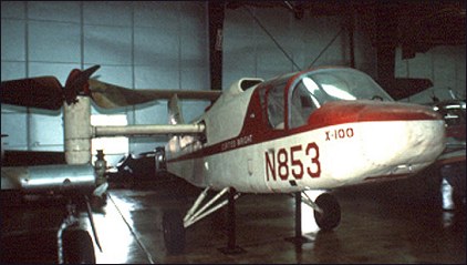
The X-100's basic configuration was a high wing with T-tail and conventional landing gear. The fuselage was 8.6m long and consisted of welded tube construction. The small, shoulder mounted wing, with a span of only 4.9m and an area of 2.1m2, had a very heavy wing loading of 560kg/m2. This was intentional so that the radial force produced by props could be demonstrated beyond any doubt. A three bladed, 3m diameter propeller was mounted on a gimbaled nacelle at each wing tip, and the two props rotated in opposite directions to balance yawing moments. Gross weight was 1580kg. The two-place cockpit had side by side seating. A rectangular engine intake was just behind the cockpit on the top of the fuselage. The T-tail, with an area of 2.1m2, was chosen to keep the stabilizer out of the props' slipstream, giving the X-100 an overall height of 3.28m.
To control pitch and yaw during hover, the engine exhaust was ducted out the rear of the fuselage and could be vectored up or down, and left or right by a device called a jetivator. This device was chosen for simplicity and to reduce weight. As a control effector, the jetivator could produce 63kg of pitch force and 18kg of yaw force. Roll control during hover was by differential control of the prop pitch. Altitude control was by means of the throttle.
The X-100 originally had a very rigid conventional landing gear. It eventually was replaced by tricycle gear to improve landing characteristics.
The props were made of foamed plastic molded onto a metal shank and covered with a layer of urethane elastomer. Blades were wide and had a considerable amount of twist to maximize the amount of radial lift. The relatively low tip speed of 200m/s in hover minimized the amount of noise.
The nacelles could rotate from pointing vertical to 12 degrees above horizontal. They rotated forward slowly at 2 degrees per second to allow the pilot to adjust power and attitude in order to prevent settling during the transition to cruise flight. They rotated back to vertical at 5 degrees per second.
Keeping with Curtiss-Wright's philosophy of building all major systems, management wanted to use a Curtiss-Wright developed or license-built engine. However, program managers hated to use internal funds to design a new engine. Originally, they considered a French Turbomecca Artouse, producing about 400hp. It was abandoned during the design phase in favor of a Lycoming YT-53-L-1 turboshaft engine of either 650 or 825 horsepower (references varied). The U.S. Army, who had numerous YT-53-L-1 engines on hand, loaned two of them for the X-100 project. In exchange, Curtiss-Wright agreed to write a report on the engines' performance. The fuselage had to be enlarged to accommodate the Lycoming engine, but this was not a significant expense considering the money saved with the engines loaned from the Army.
The design process started in February 1958. The first prop assembly was fabricated soon after and tested in NASA's 12m x 24m wind tunnel starting in October 1958. It was run through the expected power operating range and at shaft angles from 0 to 90 degrees. These tests demonstrated that thrust in hover would be 10 percent below prediction (which was later confirmed in flight test), but there was enough excess thrust that the 10 percent loss was acceptable. Preliminary wind tunnel tests using models were performed at the Massachusetts Institute of Technology, then a powered model was run in the wind tunnel to determine stability and control characteristics. Tests using the actual aircraft eventually were run in NASA's 12m x 24m wind tunnel. Reasonable correlation was achieved between wind tunnel tests and flight tests.
Roll out of the completed X-100 occurred on December 22, 1958, at Curtiss-Wright's Caldwell, NJ, facility, and the first engine run was performed on January 14, 1959. The first hover was made in a tether rig on April 20, 1959, to verify control power and feel. The first free hover test was performed on September 12, 1959, but extra weight was added to prevent the X-100 from getting out of ground effect. After three days of testing, hover flights of up to 20 minutes duration were made. The outflow velocities of air along the ground at various distances from the hovering X-100 proved to be similar to those of a helicopter of similar weight.
Hover proved to be difficult for several reasons. The pitch and yaw thrust provided by the jetivator was insufficient. Roll and yaw motions tended to couple together. The throttle was used to maintain height during hover, and lags in the engine response further compounded the problem. The X-100 also tended to weathervane into the wind during hover due to yaw moments produced by the wind hitting the props at an angle, which the jetivator's yaw control could not counter adequately.
Steady hovering was possible only up to about 4m, while the X-100 was in ground effect. If maximum power was applied on the ground, the X-100 would rise to about 7.6m, settle to within a few feet of the ground, then rise again and repeat several cycles of a slowly damped oscillation in height.
The first transition from hover to forward flight was made on April 13, 1960. The transition itself was fairly simple. The pilot pressed a switch on top of the control stick to rotate the nacelles forward, then added power to prevent sinking. As the nacelles rotated, the X-100 picked up 30km/h of airspeed for each 10 degree of tilt. The conversion was done at 0.9 to 1.5m of altitude and very slowly to prevent settling to the ground. The nacelles were rotated down in 5 degree increments until a speed of 290km/h was achieved with the nacelle at a 15 degrees from horizontal. In general, low speed flight characteristics were unsatisfactory, especially in gusty air. The X-100 demonstrated a high pitch-up moment as forward speed increased, but directional stability, roll control, and longitudinal maneuvering were good in flight at 110km/h. At low altitude and up to 110km/h, the X-100 was notably free of mechanical vibration. Testing at altitude showed the aircraft to be buffet and stall free over a large range of angles of attack.
STOL take-offs and landings were made with nacelle angle at 20 degrees from the vertical. Directional control was poor and was a problem during ground run. Smooth touch-downs also were difficult, much of the problem being caused by the landing gear being too stiff. There was considerable bouncing even at low touchdown speeds.
The basic test program was completed on July 21, 1960. Test pilots from NASA visited Curtiss-Wright and flew the X-100 on August 12 and 13. This concluded test operations for the X-100 at the Caldwell, NJ, facility.
With Curtiss-Wright satisfied that they had proven the radial lift concept, they turned the X-100 over to NASA. It was shipped to the Langley Research Center in October of 1960. However, it was not really used to test flight characteristics, but to study the effects of downwash on several types of ground surfaces, such as snow, grass, pavement, and packed dirt. NASA also studied problems associated with visibility in snow during hover and slow forward transition. This role, too, was finished by October 1961.
Following the completion of tests at Langley, the X-100 was donated to the Smithsonian Institution. During its short career, the X-100 completed a total of 14 hours flying time and 220 hours of ground engine run time. It successfully proved the radial force concept, the feasibility of tilting nacelles, and low noise levels. It successfully showed the value of using a demonstrator aircraft to highlight technical concerns quickly and to reduce risks for higher cost development programs.
S.Markman & B.Holder "Straight Up: A History of Vertical Flight", 2000